
Plasma jet generating device

A technology for generating device and plasma, applied in the direction of plasma, electrical components, etc., can solve the problems of unstable performance, difficult to adjust parameters, complex plasma structure, etc., and achieve the effects of simple structure, stable discharge and low cost

Active Publication Date: 2018-11-06
九未实业(上海)有限公司
View PDF12 Cites 0 Cited by
  • Summary
  • Abstract
  • Description
  • Claims
  • Application Information

AI Technical Summary

Problems solved by technology

[0007] The purpose of the present invention is to provide a plasma jet generation device to solve the problems in the field that the plasma structure generated by the normal pressure radio frequency plasma generation device is complex, the performance is unstable, and the parameters are difficult to adjust.

Method used


Image

  • Plasma jet generating device
  • Plasma jet generating device

Examples


Embodiment Construction

[0032] Before describing the various embodiments of the present invention, some terms are explained. In the description and claims, when describing A and B as "fluidly coupled", it means that there is a fluid passage between A and B through which fluid (for example, gas) can flow; when describing A and B When B is "electrically coupled", it means that there is a conductive path between A and B through which current can flow; mechanically) connected. In the specification and claims, when the length of an object A in one dimension is significantly greater than the length of the object A in other dimensions, the direction in which this dimension lies is referred to as the "longitudinal direction" of the object A. For example, for an elongated cylindrical shape, its axial direction is called its "longitudinal direction" because its axial length is significantly greater than its cross-sectional diameter.

[0033] The present invention will be described in detail below in conjunct...


PUM


Abstract

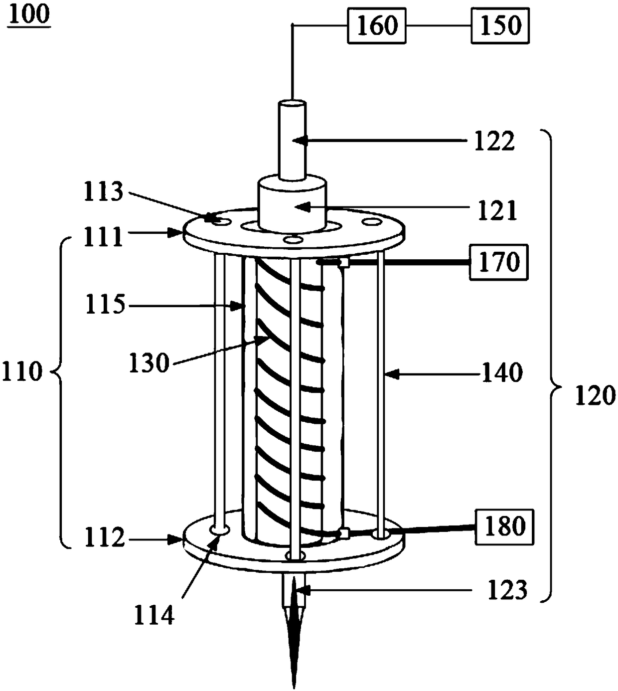
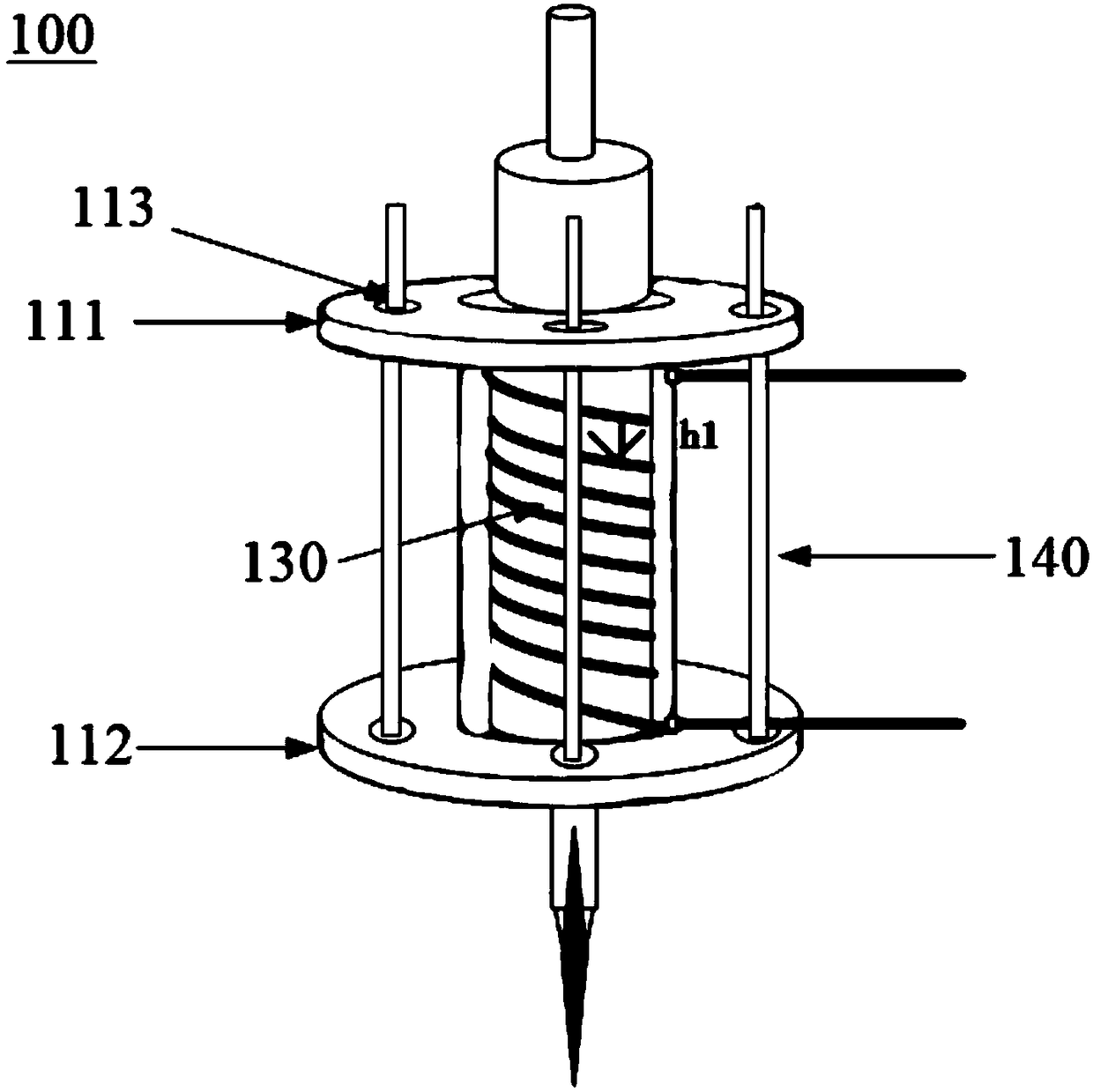
The invention relates to a plasma jet generating device. The plasma jet generating device comprises a telescopic component (110) and a medium tube component (120), wherein the telescopic component (110) can telescope along the longitudinal direction, and is provided with a hollow space in a cut-through manner along the longitudinal direction; the medium tube component (120) is arranged in the hollow space in a penetrated manner along the longitudinal manner, a gas channel in the cut-through manner along the longitudinal direction is formed in the interior of the medium tube component (120), aspiral antenna (130) along the longitudinal direction is wound on the side surface of the medium tube component (120), and the longitudinal length of the spiral antenna (130) can change through the telescoping of the telescopic component (110). Compared with the prior art, the longitudinal length of the spiral antenna can be changed conveniently, so that plasma parameters are conveniently adjusted, the discharging is more stable, the device can be preferably applicable for various application scenarios, and the device is simple in structure and low in cost and can be widely popularized and used.

Description

technical field [0001] The invention relates to the field of plasma technology, in particular to a plasma jet generating device. Background technique [0002] Plasma is the closest state to gas. Plasma can be generated by ionizing gas. Therefore, "ionized gas" is plasma, which can also be called "the fourth state of matter" besides solid, liquid, and gaseous states. [0003] The composition of the plasma contains a large number of highly active substances (for example, charged particles, O, OH, NO and O3, etc.). The high-energy particles in the plasma are easy to react with the surface of the material to be treated to achieve surface modification. Therefore, plasma technology has been widely used in many fields such as material surface treatment, waste treatment, nanocatalysis and so on. [0004] Low-temperature plasma generation methods (eg, corona discharge, glow discharge, arc discharge, spark discharge, dielectric barrier discharge) and the like are often used to gene...

Claims


Application Information

Patent Timeline
Patent Type & Authority Applications(China)
IPC IPC(8): H05H1/30
CPCH05H1/30
Inventor 昌锡江徐涛王大伟梁逸轩方玲
Owner 九未实业(上海)有限公司
Learn More