
Linear frequency modulation continuous wave system based on chaotic coding frequency agility and application method thereof

A technology of frequency modulation continuous wave and application method, which is applied in the direction of radio wave measurement system, instrument, etc., can solve the problems of complex algorithm signal signal processing time, weight, volume limitation, inapplicability, etc., and achieve the improvement of anti-intercept ability and signal processing Simple algorithm and short time-consuming effect

Inactive Publication Date: 2018-11-09
NANJING UNIV OF SCI & TECH
View PDF6 Cites 16 Cited by
  • Summary
  • Abstract
  • Description
  • Claims
  • Application Information

AI Technical Summary

Benefits of technology

This new technology allows an improved version of a missile's radar called LiFAR (Low Frequency Active Radars) without being affected negatively or affect its performance significantly during flight due to factors like beam pointing accuracy and fuel pressure control. By changing certain parameters such as antenna orientation angle, target direction, and altitude, this technology can improve detection capabilities even when there are multiple targets at once on different locations within the airspace around them. Additionally, Chooquist sequences have been used instead of binary codes to simplify the process of decoding signals sent through these systems while still maintaining their effectiveness against jamming attacks. Overall, this innovation enhances both defense capability and coordination between firefight operations effectively.

Problems solved by technology

This patented technical problem addressed in this patents relates to improving the accuracy of electronic countermeasures like radios without being able to deceit or prevent their use due to unwanted sources called clutter. Current methods involve modifying the transmitter waveshape pattern to avoid these issues, but they can be limited when dealing with dynamic disturbances caused by pulsation.

Method used


Image

  • Linear frequency modulation continuous wave system based on chaotic coding frequency agility and application method thereof
  • Linear frequency modulation continuous wave system based on chaotic coding frequency agility and application method thereof
  • Linear frequency modulation continuous wave system based on chaotic coding frequency agility and application method thereof

Examples


Embodiment Construction

[0033] The present invention will be further described below with reference to the accompanying drawings.

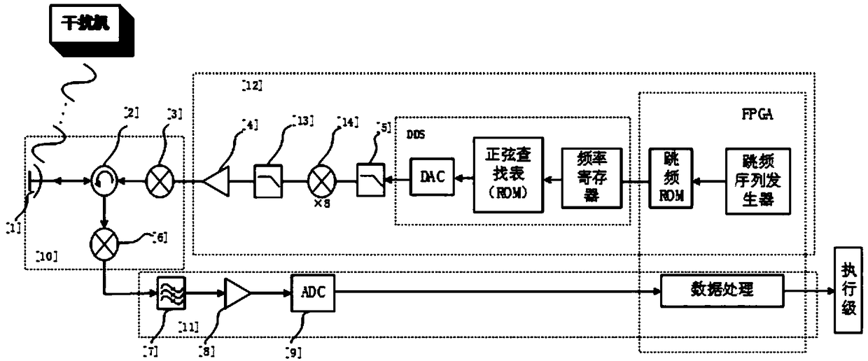
[0034] The illustrated embodiment of the present invention, with reference to figure 1 Shown is a frequency-agile linear frequency modulation continuous wave system based on chaotic coding, a continuous wave frequency modulation detector front-end module 10 , a coded signal generation module 12 , and an intermediate frequency signal processing module 11 .

[0035] The front-end module 10 of the continuous wave FM detector includes a transceiver antenna 1 , a circulator 2 , an up-converter 3 , and a mixer 6 . An up-conversion signal input interface is provided to be connected to the low noise amplifier 4, and an intermediate frequency signal output interface is provided to be connected to the band-pass filter. The front-end module of the CW FM detector works in the X-band through the up-converter, and the signal frequency hopping bandwidth can reach about 1GHz.

[0036]...


PUM


Abstract

The invention discloses a linear frequency modulation continuous wave system based on chaotic coding frequency agility and an application method thereof. The system comprises a detector front-end module which transmits a chaotic coding continuous wave frequency modulation detection signal after up-conversion and also receives a target intermediate frequency signal outputted after down-conversion of echoes; a DDS-based signal generator which is used for outputting control word DDS frequency agility linear frequency modulation continuous wave signals through the FPGA; and a digital radio frequency memory (DRFM) which is used for storing, copying, modulating and forwarding the intercepted signal, wherein the deception interference signals have great interference effect for the linear frequency modulation continuous waves. The linear frequency modulation continuous wave are optimized by using the sensitivity, the randomness and great auto-correlation and cross-correlation of the initial value of chaotic coding from the waveform design perspective, chaotic coding frequency hopping is performed on the frequency modulation center frequency and the law of agility is difficult to be intercepted by the enemy so that the anti-deception interference can be realized. The anti-interference capacity of the self-detector can be enhanced from the waveform design perspective and the system has important meaning for the field of short range detection.

Description


Claims


Application Information

Patent Timeline
Owner NANJING UNIV OF SCI & TECH
Learn More