
Ultrasound imaging apparatus

a technology of ultrasound and echogram, applied in the field of ultrasound imaging apparatus, can solve the problems of deteriorating the distance resolution of the signed echogram, difficult to obtain a signed echogram that describes plaques formed thinly on the vascular endothelium, etc., and achieves excellent distance resolution and excellent signed echogram

Inactive Publication Date: 2009-02-12
HITACHI LTD
View PDF4 Cites 1 Cited by
  • Summary
  • Abstract
  • Description
  • Claims
  • Application Information

AI Technical Summary

Benefits of technology

[0013]The signed echogram obtained according to the aspect of the present invention is produced by use of an ultrasound pulse that uses the entire bandwidth of an ultrasound transducer. The signed echogram thus produced reflects the acoustic impedance of the object to be imaged without sacrificing the excellent distance resolution that is made possible by the above-mentioned use of the ultra sound pulse. Accordingly, the ultrasound imaging apparatus provided according to the aspect of the present invention is capable of producing such an excellent signed echogram.

Problems solved by technology

The method of the conventional technique, however, has its own drawbacks.
This in turn deteriorates the distance resolution of the signed echogram in comparison to the echogram obtained by way of the envelope detection.
As a result, when this conventional method is employed without any improvement, it is difficult to obtain a signed echogram that describes such things as plaques formed thinly on the vascular endothelium.

Method used


Image

  • Ultrasound imaging apparatus
  • Ultrasound imaging apparatus
  • Ultrasound imaging apparatus

Examples


example 1

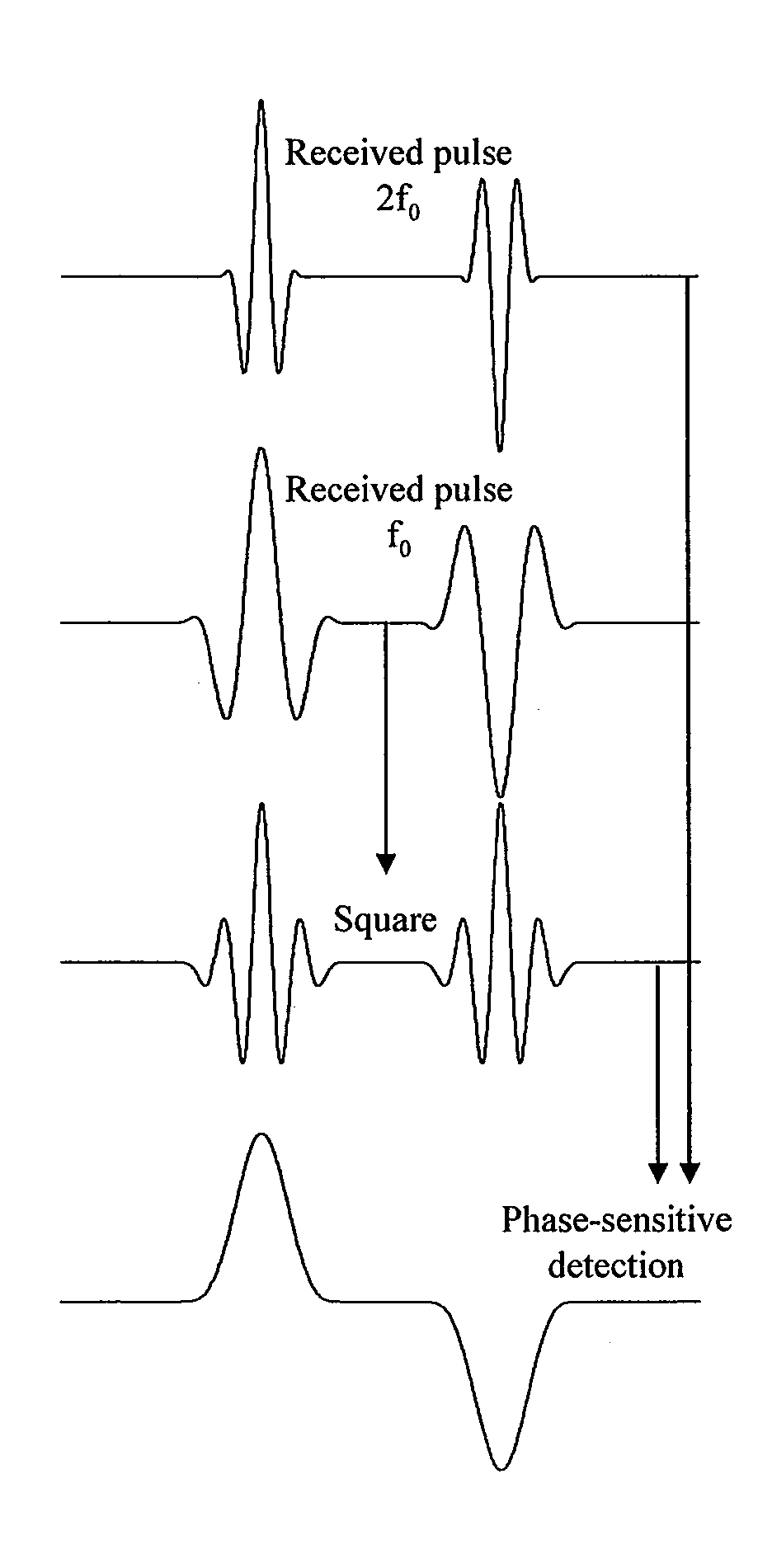
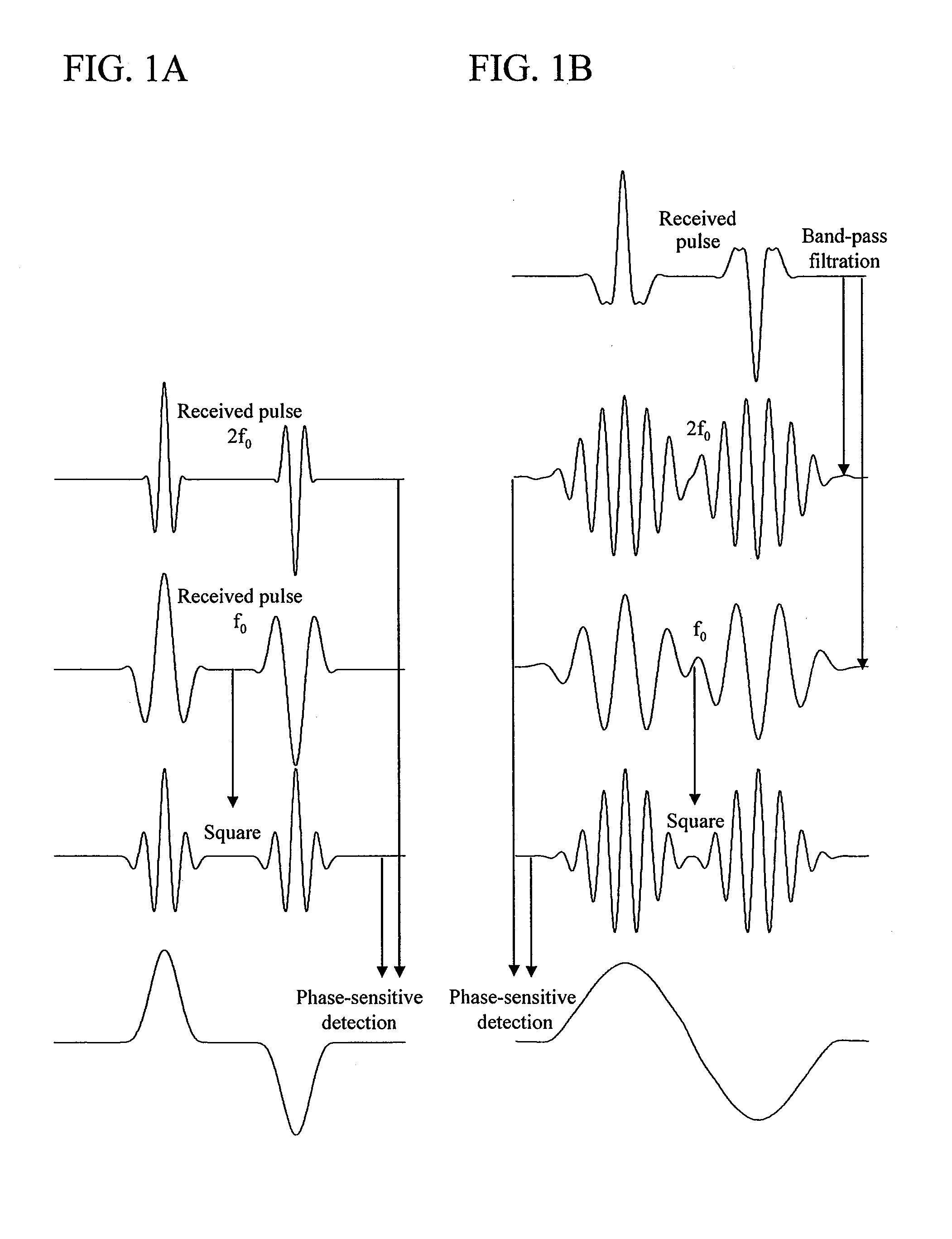
[0034]FIG. 5 is a diagram showing an example of the configuration of an ultrasound imaging apparatus that produces a signed echogram in Example 1 of the present invention. In this Example 1, a signed echo signal for the object to be examined is obtained, as shown in FIG. 1A, in the following way. Firstly, an ultrasound pulse having a center frequency of a fundamental frequency f0 is transmitted, and an echo wave produced by the reflection at an acoustic-impedance interface within the object to be examined is received. In addition, an ultrasound pulse having a center frequency of a second harmonic frequency 2f0 is transmitted, and, similarly, an echo wave produced by the reflection at an acoustic-impedance interface within the object to be examined is received. On the basis of these two received echo signals obtained in this way, a signed echo signal for the object to be examined is generated.

[0035]An ultrasound probe 1 transmits an ultrasound pulse to an object to be examined (not i...

example 2

[0046]FIG. 6 is a diagram showing an example of the configuration of an ultrasound imaging apparatus that produces a signed echogram in Example 2 of the present invention. While Example 1 is a configuration example of the apparatus that produces a signed echogram by a method described with reference to FIG. 1A, Example 2 is a configuration example of the apparatus that produces a signed echogram by a method described with reference to FIG. 3A. To put it other way, a difference between Examples 1 and 2 exists in the combination of the center frequencies of the ultrasound pulses that are transmitted and received. The way of signal processing that accompanies each combination also differs between Examples 1 and 2. In Example 2, a signed echo signal for the object to be examined is obtained, as shown in FIG. 3A, in the following way. Firstly, an ultrasound pulse having a center frequency of nf0 is transmitted, and an echo wave produced by the reflection at an acoustic-impedance interfac...


PUM


Abstract

With a natural number n, an ultrasound pulse having a center frequency of nf0 is transmitted, and an echo wave produced by the reflection at an acoustic-impedance interface within the object to be examined is received. Another ultrasound pulse having a center frequency of (n+1) f0 is transmitted, and, similarly, an echo wave produced by the reflection at an acoustic-impedance interface within the object to be examined is received. The received echo signal which has a center frequency of nf0 is raised to the power of (n+1) in a self-multiplication unit. Meanwhile, The received echo signal having a center frequency of (n+1) f0 is raised to the power of n in another self-multiplication unit. Each multiplication produces a signal having a center frequency of n (n+1) f0. A signed echo signal is obtained by a phase-sensitive detection between the two obtained signals.

Description

CLAIM OF PRIORITY[0001]The present application claims priority from Japanese application JP 2007-206936 filed on Aug. 8, 2007, the content of which is hereby incorporated by reference into this application.BACKGROUND OF THE INVENTION[0002]1. Field of the Invention[0003]The present invention relates to an ultrasound imaging apparatus used for obtaining, by use of ultrasonic waves, an echogram of the object to be examined.[0004]2. Description of the Related Art[0005]With an ultrasound imaging apparatus for medical diagnostic imaging and by the ultrasonic pulse-echo method, almost real-time images, such as tomograms of soft tissue in a living body and images of bloodstream flowing in a living body, can be displayed on and observed through the monitor. In addition, ultrasound imaging apparatuses are recognized as safer means for medical diagnostic imaging than radiologic diagnostic imaging apparatuses. Such recognition is based on the fact that the ultrasound apparatuses do not require ...

Claims


Application Information

Patent Timeline
Patent Type & Authority Applications(United States)
IPC IPC(8): A61B8/00
CPCG01S15/8952G01S7/52046
Inventor UMEMURA, SHINICHIROAZUMA, TAKASHI
Owner HITACHI LTD
Learn More