Aerosol generating system with separate capsule and vaporizing unit

A technology of aerosol generation and evaporation unit, which is applied in the manufacture of cigars, tobacco, food science, etc., and can solve the problems of expensive tube production

Active Publication Date: 2018-11-09
PHILIP MORRIS PROD SA
View PDF7 Cites 4 Cited by
  • Summary
  • Abstract
  • Description
  • Claims
  • Application Information

AI Technical Summary

Problems solved by technology

[0003] However, cartridges with this arrangement can be relatively expensive to produce

Method used


Image

  • Aerosol generating system with separate capsule and vaporizing unit
  • Aerosol generating system with separate capsule and vaporizing unit
  • Aerosol generating system with separate capsule and vaporizing unit

Examples


Embodiment Construction

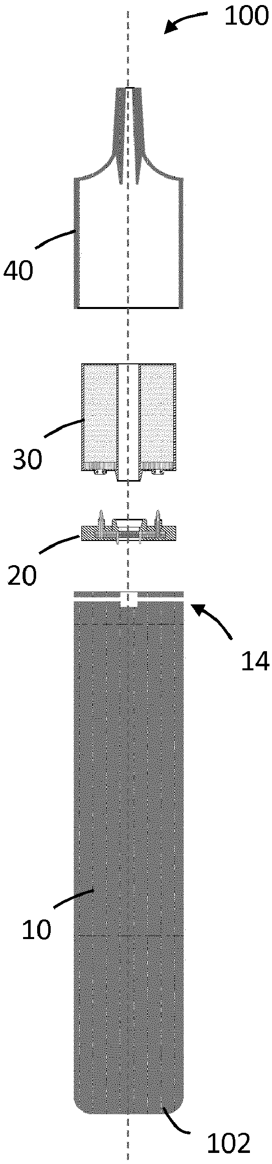
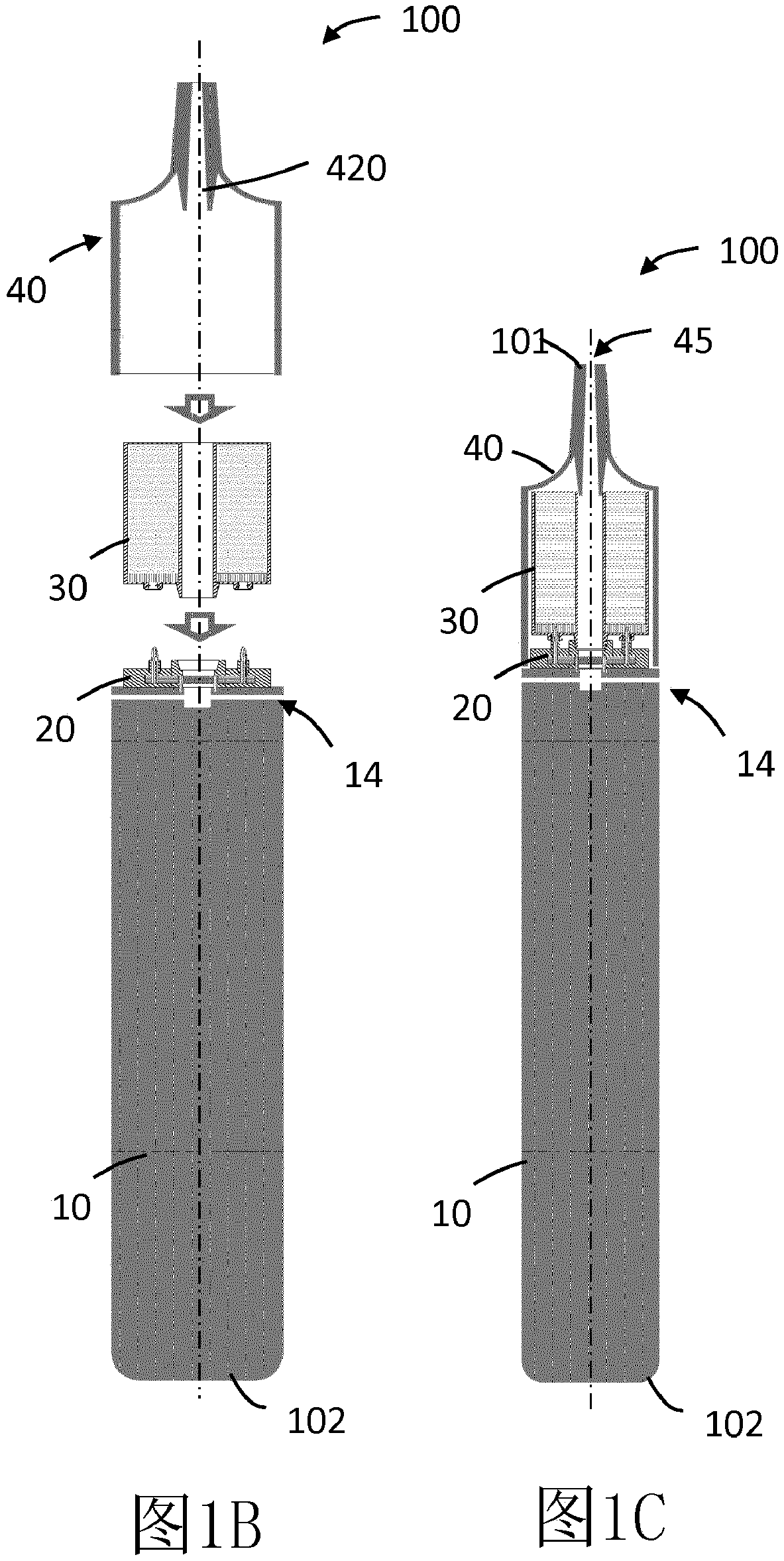
[0071] now refer to Figure 1A -C, the aerosol generating system 100 includes a battery assembly 10 , an evaporation unit 20 , a casing 30 and a cover 40 . The battery assembly 10 is releasably connectable to the evaporation unit 20 . The evaporation unit 20 is releasably connectable to the enclosure 30 . The cover 40 is disposed over the evaporation unit 20 and the enclosure 30 . Cover 40 is releasably secured in place relative to evaporation unit 20 and enclosure 30 . In some examples, the cover may be releasably connectable to the battery assembly, and the cover helps to hold the evaporation unit and enclosure in place when the cover is connected to the battery assembly.

[0072] The system has a distal end 102 and an oral end 101 . The battery assembly 10 includes a housing defining an air inlet 14 and a channel communicating with the inlet. When the user draws on the mouth port 101, air can be drawn through the air inlet 14 and the passages in the housing of the batte...


PUM


Abstract

An aerosol-generating system (100) includes a capsule (30, 300A, 300B) and a releasably connectable vaporizing unit (20). The capsule (30, 300A, 300B) comprises a distal end and a reservoir (300) containing an aerosol-generating substrate (360). The vaporizing unit (20) comprises a housing (240), and a heating element (220) and a liquid transfer element (210, 218) disposed in the housing. The heating element (220) is configured to heat liquid in the liquid transfer element (210, 218). The housing of the vaporizing unit (20) has a proximal end. A portion of the liquid transfer element (210, 218) extends beyond the proximal end of the housing (240). The vaporizing unit (20) is configured such that the liquid transfer element (210, 218) is the first portion of the vaporizing unit (20) to penetrate into the reservoir (300) of the capsule (30, 300A, 300B) as the distal end of the capsule (30, 300A, 300B) is moved towards the proximal end of the vaporizing unit (20).

Description

technical field [0001] The present invention relates to multi-component electrically heated aerosol generating systems and related devices, articles and methods. Background technique [0002] One type of aerosol-generating system is an electrically operated hand-held aerosol-generating system. Known hand-held electrically operated aerosol generating systems comprise a device portion including batteries and control electronics, a replaceable cartridge portion including an aerosol generating substrate supply, and an electrically operated vaporizer. A cartridge comprising an aerosol-generating substrate supply and a vaporizer is sometimes referred to as a "cart". Vaporizers typically comprise a coil of heating wire wrapped around an elongated core immersed in a liquid aerosol-generating matrix. The barrel portion typically forms a mouthpiece over which a user draws to cause the aerosol to flow into his mouth. [0003] However, cartridges with this arrangement can be relative...

Claims


Application Information

Patent Timeline
Patent Type & Authority Applications(China)
IPC IPC(8): A24F47/00A24F40/10A24F40/42A24F40/485
CPCA24F40/10A24F40/42A24F40/485A24F40/46A24D1/02A24F40/00A24F47/00A24F40/44
Inventor E·福斯
Owner PHILIP MORRIS PROD SA
Why Eureka
Try Eureka