Drainage structure of washing machine

A drainage structure and washing machine technology, applied in the field of washing machines, to achieve the effect of increasing the volume and improving the washing capacity

Active Publication Date: 2018-11-13
QINGDAO HAIER WASHING MASCH CO LTD +2
View PDF5 Cites 5 Cited by
  • Summary
  • Abstract
  • Description
  • Claims
  • Application Information

AI Technical Summary

Problems solved by technology

In the washing machine drainage structure of the present invention, an airtight inner cylinder cover is provided at the mouth of the inner cylinder, and a driving mechanism that can drive the inner cylinder cover to open is provided between the inner cylinder cover and the door cover, so that the inner cylinder cover can be opened The water in the inner cylinder is discharged from the opened inner cylinder mouth, so as to solve the problem of washing water discharge in the inner cylinder, and then realize the sealing of the rotatable inner cylinder mouth, the water in the inner cylinder does not leak out during the normal working process of the washing machine, and the washing machine When draining, the washing water in the inner cylinder is drained by opening the mouth of the inner cylinder; at the same time, the inner and outer cylinders of the drum washing machine are combined into one, so as to realize the purpose of expanding the washing capacity of the washing machine

Method used


Image

  • Drainage structure of washing machine
  • Drainage structure of washing machine

Examples


Embodiment 1

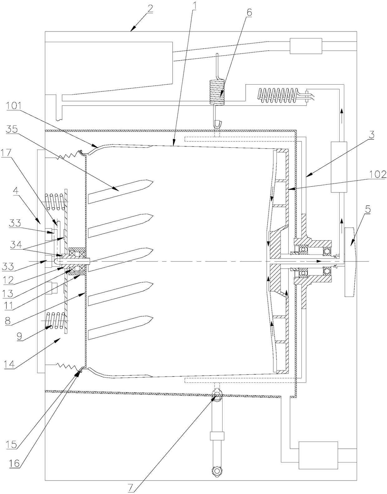
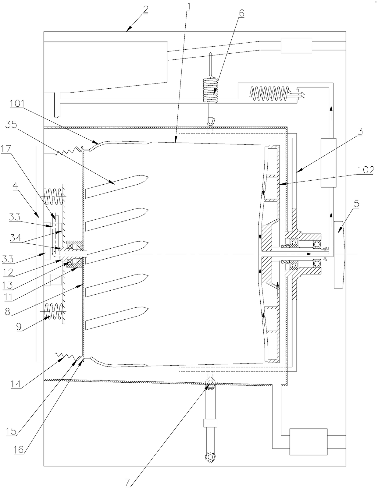
[0039] Such as figure 1 and figure 2 As shown, a drainage structure of a washing machine is introduced in this embodiment. A door cover 4 is installed on the washing machine shell 2, and the inner side of the door cover 4 is connected with the inner cylinder cover 8 through an elastic mechanism, so that the inner cylinder cover 8 is closed after the door cover 4 is closed. The cylinder cover is pressed tightly on the inner cylinder mouth 101 by the elastic mechanism, so that the inner cylinder 1 is sealed; a driving mechanism is provided between the inner cylinder cover 8 and the door cover 4, and the elastic force of the elastic mechanism on the inner cylinder cover 8 is overcome when the driving mechanism is working. The inner cylinder cover 8 is separated from the inner cylinder mouth 101, and the water in the inner cylinder 1 is discharged from the opened inner cylinder mouth 101.

[0040] In this embodiment, the drive mechanism includes an electromagnet 39 installed on ...

Embodiment 2

[0050] The difference between this embodiment and Embodiment 1 is that the drive mechanism includes a drive motor installed on the door cover, and the output end of the drive motor is connected to the inner cylinder cover through a crank slider device, so that the crank slides when the drive motor is working. The block device pulls the inner cylinder cover 8 to move toward the door cover 4, so that the inner cylinder cover 8 is separated from the inner cylinder mouth 101.

[0051] By arranging a driving mechanism between the door cover and the inner cylinder cover, the inner cylinder cover can also be driven to open by the driving mechanism, so that the inner cylinder cover can be opened and the water contained in the inner cylinder can be discharged from the mouth of the inner cylinder.

[0052] In this embodiment, the driving mechanism is arranged at the lower part of the inner cylinder cover 8, so as to pull the lower part of the inner cylinder cover 8 to move toward the doo...

Embodiment 3

[0055] In this embodiment, in order to realize the sealing at the mouth 101 of the inner cylinder when the washing machine is working, the following settings are made:

[0056] Such as figure 1 As shown, a washing machine, a door cover 4 is installed on the washing machine shell 2, and the door cover 4 is relatively rotatably connected with the inner cylinder cover 8 through the elastic mechanism, so that the elastic mechanism provides the inner cylinder cover 8 with the door cover 4 closed. The locking elastic force makes the inner cylinder cover 8 and the inner cylinder mouth 101 in sealing contact, and makes the inner cylinder cover 8 rotate together with the inner cylinder 1, so that the inner cylinder cover 8 is fastened to the inner cylinder mouth 101 after the door cover 4 is closed. The purpose of inner cylinder 1 sealing.

[0057] Through the above settings, the inner cylinder cover at the mouth of the inner cylinder is sealed by elastic force. During the washing pro...


PUM


Abstract

The invention relates to a drainage structure of a washing machine. A door cover is installed on a washing machine shell. The inner side of the door cover is connected with an inner tub cover throughan elasticity mechanism so that the inner tub cover can be compressed on an opening of an inner tub through the elasticity mechanism after the door cover is closed, and the inner tub is sealed; a driving mechanism is arranged between the inner tub cover and the door cover, elasticity of the elasticity mechanism for the inner tub cover is overcome when the driving mechanism works so that the innertub cover can be disengaged from the opening of the inner tub, and water in the inner tub is drained from the open opening of the inner tub; In this way, the inner tub is sealed in the inner tub rotating process, and the effect of normally draining water contained in the inner tub during drainage is achieved; meanwhile, the inner tub cover can open or close the opening of the inner tub under the effect of the driving mechanism; in addition, the inner tub does not need to be sleeved with an outer tub, the volume of the inner tub is increased, and the washing capacity of the washing machine is improved.

Description

technical field [0001] The invention belongs to the technical field of washing machines, and in particular relates to a washing machine with only a rotatable and water-holding inner cylinder, in particular to a drainage structure of the washing machine. Background technique [0002] In the prior art, a drum washing machine generally includes an inner cylinder and an outer cylinder that fit each other, the outer cylinder is sealed to hold water, the inner cylinder is used to hold clothes, and the inner cylinder is rotated to beat and wash the clothes; at the same time, the inner cylinder is Set the dehydration hole so that the water in the outer cylinder flows into the inner cylinder through the dehydration hole to soak the clothes in the inner cylinder, the water in the inner cylinder flows out to the outer cylinder through the dehydration hole, and the moisture on the clothes in the inner cylinder is dehydrated when the inner cylinder rotates at high speed The hole is disch...

Claims


Application Information

Patent Timeline
Patent Type & Authority Applications(China)
IPC IPC(8): D06F39/08
CPCD06F39/083
Inventor 劳春峰许升李以民吕艳芬郝兴慧吴迪
Owner QINGDAO HAIER WASHING MASCH CO LTD
Why Eureka
Try Eureka