
Projection device for elevator room and use method of projection device

A technology for projection equipment and elevator rooms, which is applied in the field of projection equipment, can solve problems such as affecting projection effects, reducing the practicability of projection equipment, and consuming energy, and achieves the effects of good projection effects, simple structure, and convenient operation

Inactive Publication Date: 2018-11-13
WUHU INST OF TECH
View PDF14 Cites 3 Cited by
  • Summary
  • Abstract
  • Description
  • Claims
  • Application Information

AI Technical Summary

Problems solved by technology

[0002] Projection equipment is an optical instrument that uses optical elements to enlarge the outline of a workpiece and projects it onto a video screen. With the development of society, people give full play to the functions of projection equipment and use projection equipment in all aspects of life. Among them, there is projection equipment in elevator rooms. With the continuous development of science and technology, people's requirements for projection equipment are getting higher and higher. Existing projection equipment can no longer meet people's needs; Disadvantages, firstly, it is inconvenient for people to adjust the angle of the projection device, which greatly reduces the practicability of the projection device; secondly, the existing projection device continues to project when the elevator stops, which consumes more energy; There is dust on the lens, which will affect the effect of projection and bring a certain impact on people's use process. Therefore, we propose an elevator projection equipment and its use method

Method used


Image

  • Projection device for elevator room and use method of projection device
  • Projection device for elevator room and use method of projection device
  • Projection device for elevator room and use method of projection device

Examples


Embodiment Construction

[0017] In order to make the technical means, creative features, goals and effects achieved by the present invention easy to understand, the present invention will be further described below in conjunction with specific embodiments.

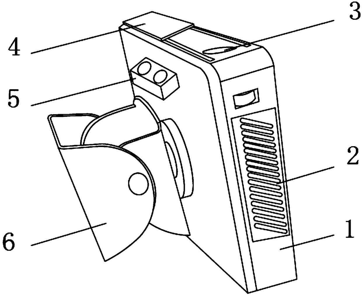
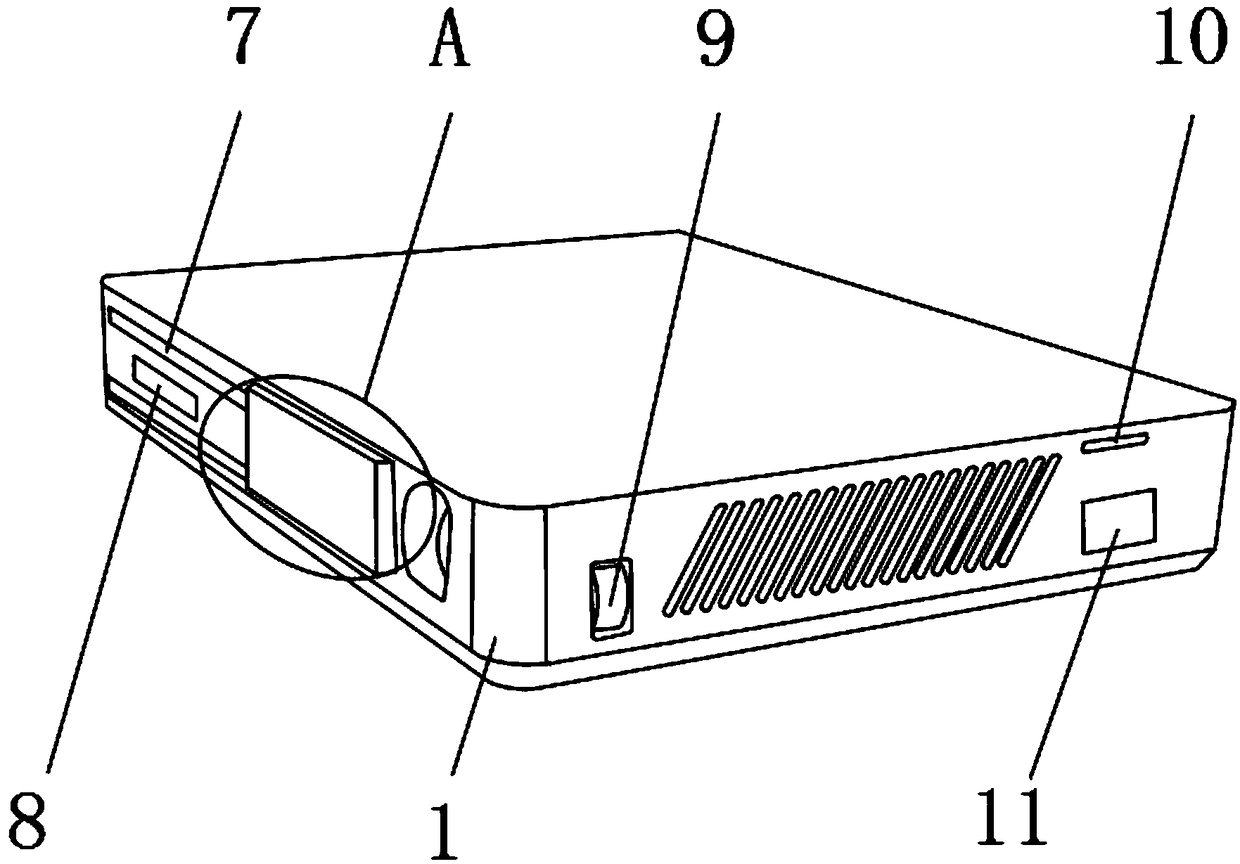
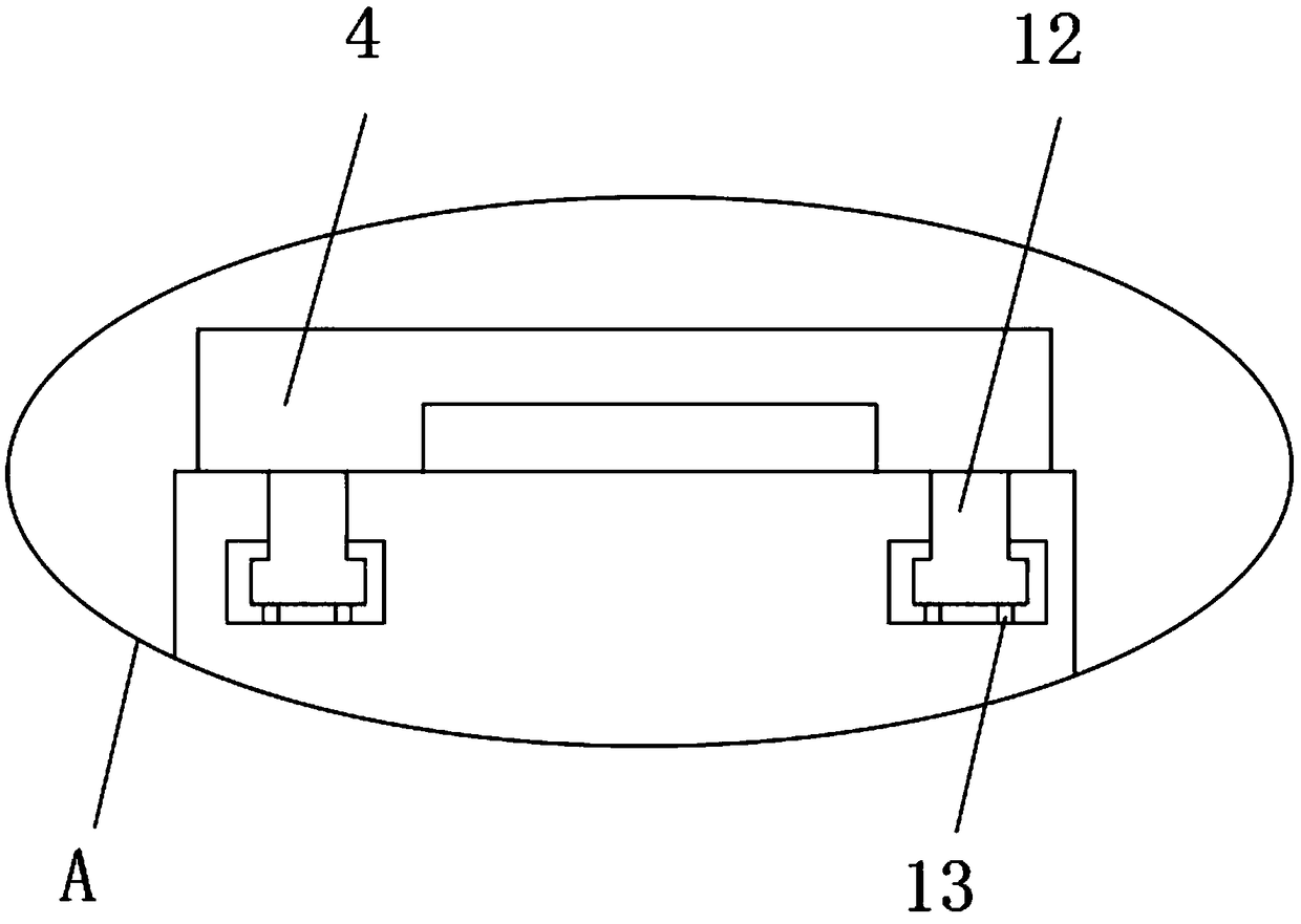
[0018] Such as Figure 1-4 As shown, a projection device in an elevator and a method of use thereof include a device casing 1, a heat sink 2 is fixedly connected to the outer surface of the front end of the device casing 1, a projection lens 3 is fixedly connected to the upper outer surface of the device casing 1, and the outer surface of the device casing 1 The outer surface of the upper end is located at the rear of the projection lens 3 and is movably connected with a sliding baffle 4, and the outer surface of one side of the equipment housing 1 is fixedly connected with a connecting block 5, and the lower side of the connecting block 5 is provided with a fixed bracket 6. One part of the equipment housing 1 The outer surface of the side is fixe...


PUM


Abstract

The invention discloses a projection device for an elevator room and a use method of the projection device. The projection device comprises a device shell, wherein a heat dissipating panel is fixedlyconnected to the outer surface of the front end of the device shell, a projection lens is fixedly connected to the outer surface of the upper end of the device shell, a sliding baffle plate is movablyconnected at the position, behind the projection lens, of the outer surface of the upper end of the device shell, a connecting block is fixedly connected to the outer surface of one side of the device shell, a fixing bracket is arranged on one side below the connecting block, and a sliding track and an infrared sensing lamp are fixedly connected to the outer surface of one side of the device shell. For the projection device for the elevator room and the use method of the projection device provided by the invention, a rotation shaft, the infrared sensing lamp and the sliding baffle plate are arranged, the projection direction of the projection device can be adjusted, meanwhile, the projection device is automatically closed when no people are in the elevator room, thus energy is saved, in addition, dust on the surface of the projection lens can be resisted, so that the projection effect of the projection device is good, and good use prospect is brought.

Description

technical field [0001] The invention relates to the field of projection equipment, in particular to a projection equipment in an elevator room and a method for using it. Background technique [0002] Projection equipment is an optical instrument that uses optical elements to enlarge the outline of a workpiece and projects it onto a video screen. With the development of society, people give full play to the functions of projection equipment and use projection equipment in all aspects of life. Among them, there is projection equipment in elevator rooms. With the continuous development of science and technology, people's requirements for projection equipment are getting higher and higher. Existing projection equipment can no longer meet people's needs; Disadvantages, firstly, it is inconvenient for people to adjust the angle of the projection device, which greatly reduces the practicability of the projection device; secondly, the existing projection device continues to project ...

Claims


Application Information

Patent Timeline
IPC IPC(8): G09F19/18G03B21/14F21V23/04
CPCF21V23/0464G03B21/14G09F19/18
Inventor 张俊孙晓雷吕嫄童彦周晶陶婧
Owner WUHU INST OF TECH
Learn More