A microwave photon down-conversion device and method

A technology of microwave photonics and frequency conversion devices, which is applied in the field of microwave photonics, can solve the problems of poor stability of light sources, high frequency of electrical local oscillator sources, and complex systems, and achieve the effects of easy frequency adjustment, flexible and variable down-conversion, and low frequency

Active Publication Date: 2021-12-10
UNIV OF ELECTRONICS SCI & TECH OF CHINA
View PDF4 Cites 0 Cited by
  • Summary
  • Abstract
  • Description
  • Claims
  • Application Information

AI Technical Summary

Problems solved by technology

This method uses a mode-locked laser to generate an optical frequency comb, which has problems such as complex system, poor light source stability and poor tuning
In the series or parallel electro-optic modulation method, the radio frequency signal and the electric local oscillator signal to be converted are respectively loaded on two different electro-optical modulators to generate a series of sidebands, and the two modulated light sidebands with adjacent frequencies pass through the photodetector. Beat frequency realizes down-conversion. Although this method solves the disadvantage of poor tuning in the optical frequency comb heterodyne method, the frequency of the electrical local oscillator source required for high-frequency RF signal processing is relatively high, making the frequency of the RF signal to be processed limited range

Method used


Image

  • A microwave photon down-conversion device and method
  • A microwave photon down-conversion device and method
  • A microwave photon down-conversion device and method

Examples


Embodiment 1

[0045] Under the same local oscillator signal conditions, different radio frequency signals are down-converted to intermediate frequency signals of different frequencies, and correspond to the intermediate frequency signals of the two value methods.

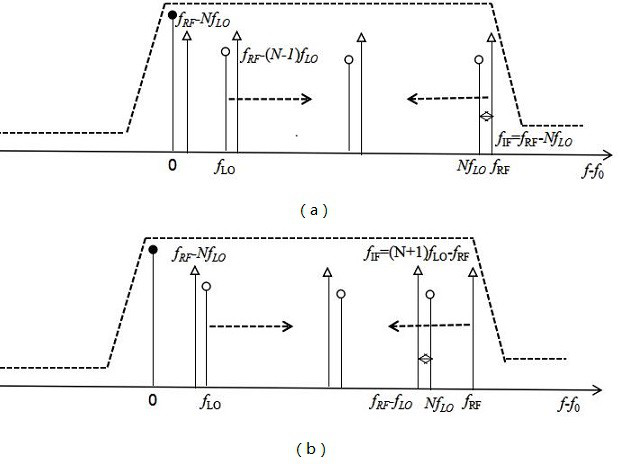
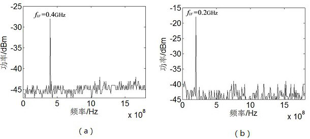
[0046] The frequency of the radio frequency signal to be frequency-converted is 40GHz and 25GHz, and the frequency of the electric local oscillator signal generated by the electric local oscillator source (8) is 3.6GHz. By adjusting the filter window of the optical band-pass filter (6), different frequencies RF signal processing. image 3 The frequency of the RF signal to be converted in (a) is 40GHz, because (40-3.6×11=0.4)IF = f RF -Nf LO =40-3.6×11=0.4GHz, corresponding figure 2 Middle (a).

[0047] image 3 The frequency of the RF signal to be converted in (b) is 25GHz, because (25-3.6×6=3.4)>(3.6 / 2), so f IF =(N+1)f LO -f RF =7×3.6-25=0.2GHz, corresponding to figure 2 Middle (b).

[0048] To sum up, under the cond...

Embodiment 2

[0050] Different LO signals downconvert the same RF signal to different IF frequencies.

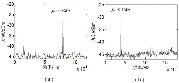
[0051] In this embodiment, the frequency of the radio frequency signal to be converted is 40 GHz, and the frequencies of the local oscillator signals generated by the electric local oscillator source (8) are respectively 2.4 GHz and 3.6 GHz, Figure 4 (a) and (b) are schematic diagrams of down-converting radio frequency signals to be frequency-converted to intermediate frequency signals of 0.8 GHz and 0.4 GHz when the local oscillator signal frequencies are 2.4 GHz and 3.6 GHz, respectively.

[0052] To sum up, by changing the frequency of the local oscillator signal, the down-conversion of the tunable microwave signal can be realized by using the device and the method.


PUM


Abstract

A microwave photonic down-conversion device and method based on bidirectional cyclic frequency shifting, involving the field of microwave photonics, in order to solve the shortcomings of traditional electrical frequency converters such as small bandwidth and large loss, and the shortcomings of optical frequency conversion technology that requires high-frequency electrical local oscillators; The device of the invention is composed of a laser, a cyclic frequency shift module and a photodetector. The cyclic frequency shift module includes a 2×2 optical coupler, a polarization controller, a dual-drive electro-optic intensity modulator, an electric local oscillator source, an optical amplifier, an optical bandpass filter, and an optically adjustable delay line; in the cyclic frequency shift module , the first-order optical sidebands of the radio frequency signal to be converted by the optical carrier and the electrical local oscillator signal move toward the opposite optical sideband at the same frequency-shifting step, and finally photoelectrically detect the opposite-frequency-shifted optical sidebands of the two nearest-neighbor frequencies to realize Frequency down-conversion of radio frequency signals: Utilizing the phase-shift frequency characteristics of the cyclic frequency shift module, by changing the frequency of the electric local oscillator source, a wide frequency range under low-frequency electric local oscillators and down-conversion of tunable microwave signals can be realized.

Description

technical field [0001] The invention relates to the technical field of microwave photonics, in particular to a microwave photon down-conversion device and a microwave photon down-conversion method. Background technique [0002] With the increasing demand for frequency bands in applications such as wireless communication, satellite communication, and radar detection, the current microwave frequency band resources are becoming more and more tense, prompting microwave communication to gradually develop into high-frequency bands. The traditional microwave mixer down-converts the frequency of the received signal to an intermediate frequency or DC with a lower frequency, thereby reducing the bandwidth requirement of the receiving end, but the microwave mixer suffers from small operating bandwidth, low isolation, large loss, and low conversion efficiency. The impact of the problem has made it increasingly difficult to meet current needs. Microwave photon frequency conversion uses ...

Claims


Application Information

Patent Timeline
Patent Type & Authority Patents(China)
IPC IPC(8): H04B10/54H04B10/556H04B10/70H04B10/50
CPCH04B10/505H04B10/54H04B10/556H04B10/70H04B2210/006
Inventor 张尚剑李智慧邹新海张旨遥张雅丽刘永
Owner UNIV OF ELECTRONICS SCI & TECH OF CHINA
Why Eureka
Try Eureka