
Electronic equipment

A technology for electronic equipment and conductive parts, applied in the field of electronic equipment, can solve problems such as electrostatic interference of electrical devices, and achieve the effect of ensuring grounding reliability

Active Publication Date: 2021-02-02
GUANGDONG OPPO MOBILE TELECOMM CORP LTD
View PDF8 Cites 0 Cited by
  • Summary
  • Abstract
  • Description
  • Claims
  • Application Information

AI Technical Summary

Problems solved by technology

Among them, the magnetic steel of the receiver is generally made of metal. If the static charge on the magnetic steel is not released, it will cause greater electrostatic interference to the electrical devices near the receiver where the electronic equipment is placed.

Method used


Image

  • Electronic equipment
  • Electronic equipment
  • Electronic equipment

Examples


no. 1 example

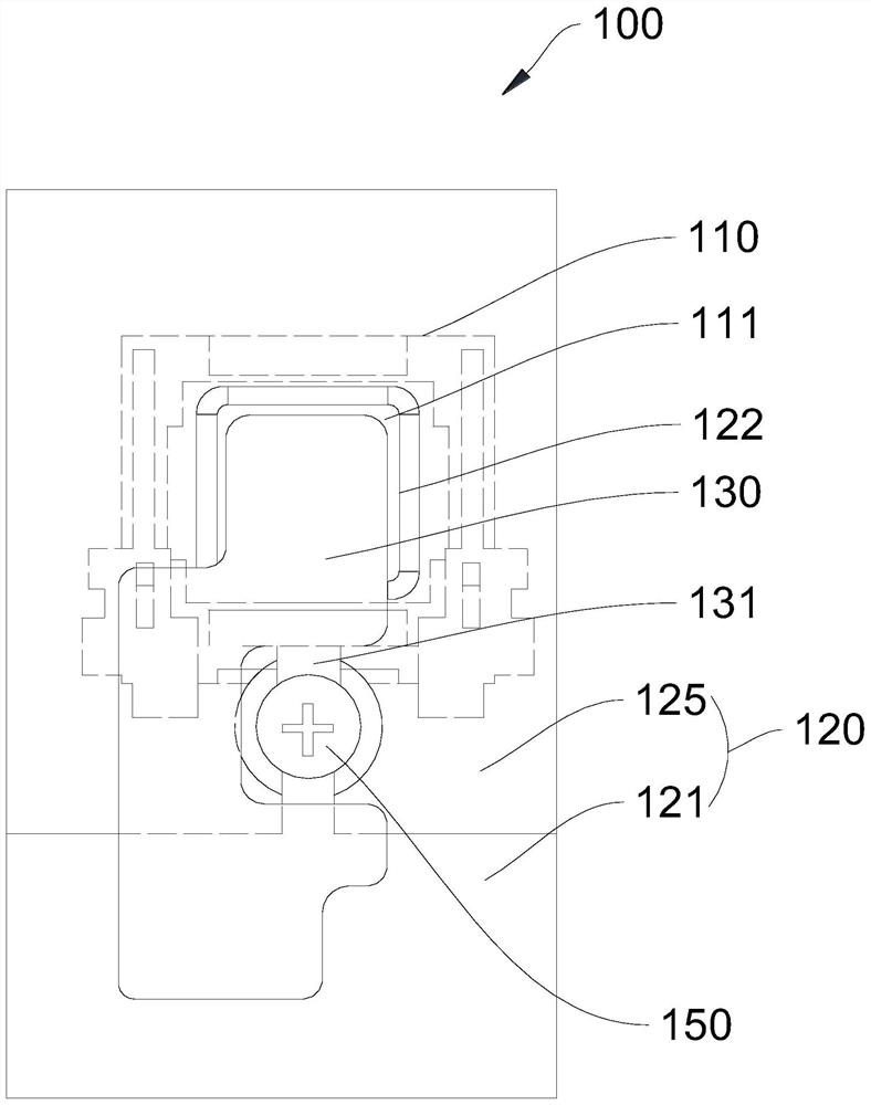
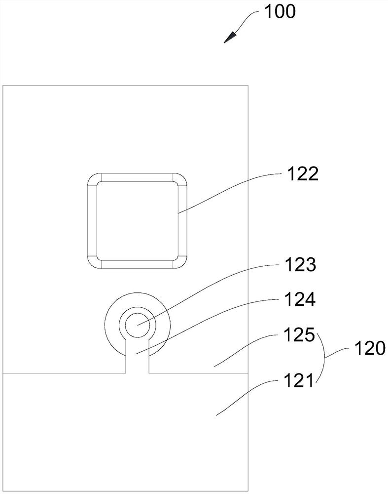
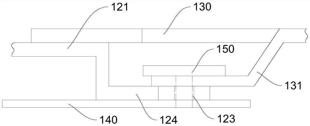
[0025] Please refer to figure 1 , figure 1 It is a schematic structural diagram of the electronic device 100 provided in the first embodiment of the present application. In some implementations, the electronic device 100 may serve as a housing or a part of the housing of an electronic device 100 such as a mobile phone.

[0026] The electronic device 100 includes a receiver 110 , a casing 120 , a conductive element 130 and a front casing metal insert 140 . The receiver 110 has a magnetic steel 111; the housing 120 has a back cover metal sheet 121, the housing 120 covers the receiver 110, and a communication hole 122 is opened at a position corresponding to the magnetic steel 111; one end of the conductive member 130 is electrically connected to the magnetic steel 111 , the other end protrudes from the communication hole 122 and is electrically connected to the back cover metal sheet 121 ; the front shell metal insert 140 is electrically connected to the back cover metal sheet...

no. 2 example

[0052] Please refer to Figure 6 , Figure 6 It is a schematic structural diagram of the electronic device 100 provided in the second embodiment of the present application.

[0053] Compared with the above-mentioned first embodiment, in this embodiment, the electronic device 100 further includes a back cover 11 , and the back cover 11 covers the back cover metal sheet 121 and the communication hole 122 . As one way, the rear cover 11 may be the rear case of the electronic device 100 or the entire casing including the rear case, and may also include components such as the middle frame and the front case of the electronic device 100 .

[0054] In this embodiment, the casing 120 may serve as a part of the middle frame or the rear case of the electronic device 100 ; the metal insert 140 of the front case may serve as a part of the front case of the electronic device 100 .

[0055] In this embodiment, the electronic device 100 may further include other structures (such as a displ...


PUM


Abstract

The embodiment of the present application discloses an electronic device, which relates to the technical field of electronic devices. The electronic equipment includes: a receiver, the receiver has a magnetic steel; a casing, the casing has a back cover metal sheet, the casing covers the receiver, and a communication hole is opened at a position corresponding to the magnetic steel; a conductive part, one end of the conductive part is connected to the magnetic steel electric Sexual connection, the other end protrudes from the communication hole and is electrically connected with the back cover metal sheet; and the front shell metal insert, the front shell metal insert is electrically connected with the back cover metal sheet, and the conductive part also has a The extension part extending from the insert is electrically connected with the metal insert of the front case. The grounding of the magnetic steel of the receiver and the metal insert of the front shell is cleverly realized through the transition of the conductive part and the metal sheet of the back cover, and the feed point of the receiver is avoided through the opening of the shell, so that the grounding reliability is guaranteed.

Description

technical field [0001] The present application relates to the technical field of electronic equipment, and more specifically, to an electronic equipment. Background technique [0002] Existing electronic devices such as mobile phones and tablet computers are provided with a variety of metal components to realize or meet various demands of the electronic devices. Among them, the magnetic steel of the receiver is generally made of metal. If the static charge on the magnetic steel is not released, it will cause relatively large electrostatic interference to the electrical devices near the receiver where the electronic equipment is placed. Contents of the invention [0003] In view of the above problems, the present application proposes an electronic device that can solve the above problems. [0004] An embodiment of the present application provides an electronic device, the electronic device includes: a receiver, the receiver has a magnetic steel; a housing, the housing has ...

Claims


Application Information

Patent Timeline
Patent Type & Authority Patents(China)
IPC IPC(8): H05F3/02
CPCH05F3/02
Inventor 袁永亮严慎波徐胜
Owner GUANGDONG OPPO MOBILE TELECOMM CORP LTD
Learn More