Bending equipment of metal stamping part

A technology for metal stamping parts and equipment, applied in the field of bending equipment for metal stamping parts, can solve the problems of high production cost of tools, inconvenient use, cumbersome operation in the bending process, etc., to improve bending efficiency, simplify complex structures, cost reduction effect

Inactive Publication Date: 2018-11-20
ANHUI KAICHENG ELECTRIC APPLIANCE CO LTD
View PDF0 Cites 5 Cited by
  • Summary
  • Abstract
  • Description
  • Claims
  • Application Information

AI Technical Summary

Problems solved by technology

[0003] In the process of metal plate processing, it is often necessary to bend the metal plate to meet the needs of installation and use. It is also a relatively common process in the metal plate processing process. However, although the bending tools used in many bending processes can realize Bending process, but the operation of the bending process is cumbersome, and the production cost of the tool is high, so it is inconvenient to use. Therefore, in order to solve such problems, we propose a bending equipment for metal stamping parts

Method used


Image

  • Bending equipment of metal stamping part
  • Bending equipment of metal stamping part
  • Bending equipment of metal stamping part

Examples


Embodiment Construction

[0017] The following will clearly and completely describe the technical solutions in the embodiments of the present invention with reference to the accompanying drawings in the embodiments of the present invention. Obviously, the described embodiments are only some, not all, embodiments of the present invention.

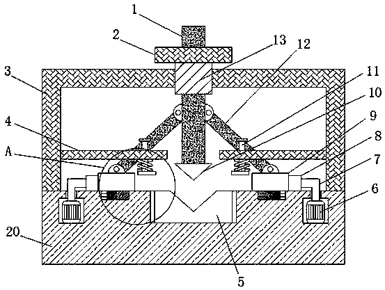
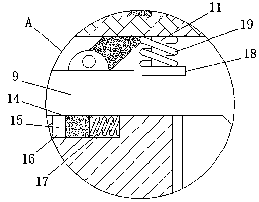
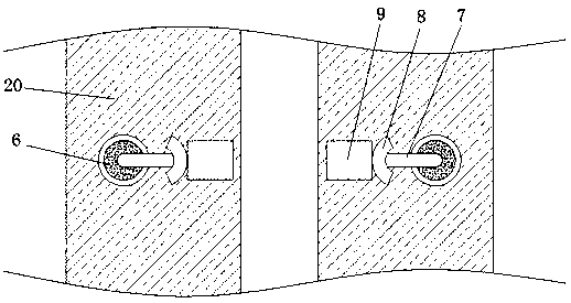
[0018] refer to Figure 1-3 , bending equipment for metal stamping parts, including a base 20, a transmission plate 5 is provided at the middle of the top of the base 20, and two symmetrically arranged motor installation slots are provided at the top of the base 20, and the two motor installation slots are located on the transmission plate 5 On both sides of the motor mounting groove, a rotating motor 6 is installed by screws, and the output shaft of the rotating motor 6 is vertically upwardly arranged, and the output shaft of the rotating motor 6 is connected with a rotating rod 7, and the rotating rod 7 The end is connected with push plate 8, and the top of describ...


PUM


Abstract

The invention discloses bending equipment of a metal stamping part. The equipment comprises a base, a conveying plate is arranged in the middle of the top end of the base, two symmetric motor mountinggrooves are formed in the top end of the base, and the two motor mounting grooves are located on the two sides of the conveying plate. Rotating motors are installed in the motor mounting grooves through screws, output shafts of the rotating motors are vertically arranged upwards, the output shafts of the rotating motors are connected with rotating rods, and the ends of the rotating rods are connected with pushing plates. Symmetric sliding grooves are formed in the top end of the base, sliding blocks are slidably connected with the interiors of the sliding grooves, and movable plates are connected to the top ends of the sliding blocks. When the equipment is used, the metal stamping part can be limited, and a series of stamping and bending operations can be carried out on the metal stampingpart. Meanwhile, the complex structure of bending equipment in the prior art is simplified, the cost is reduced, the bending efficiency of the metal stamping part can be greatly improved, and the equipment is suitable for popularization.

Description

technical field [0001] The invention relates to the technical field of bending equipment, in particular to bending equipment for metal stamping parts. Background technique [0002] The bending machine is a machine capable of bending thin plates. Its structure mainly includes a bracket, a workbench and a clamping plate. The workbench is placed on the bracket. The workbench is composed of a base and a pressure plate. The base is composed of a seat shell, a coil and a cover plate, the coil is placed in the depression of the seat shell, and the top of the depression is covered with a cover plate. When in use, the wire is energized to the coil, and after energization, an attractive force is generated on the pressure plate, so as to realize the clamping of the thin plate between the pressure plate and the base. Due to the use of electromagnetic force clamping, the pressure plate can be made into a variety of workpiece requirements, and the workpiece with side walls can be process...

Claims


Application Information

Patent Timeline
Patent Type & Authority Applications(China)
IPC IPC(8): B21D5/01B21D43/00
CPCB21D5/002B21D5/01
Inventor 崔华国张盼黄河
Owner ANHUI KAICHENG ELECTRIC APPLIANCE CO LTD
Why Eureka
Try Eureka