Small horizontal bending machine

A bending machine and horizontal technology, applied in the field of forging machinery, can solve the problems of high equipment manufacturing cost, low work efficiency, complex structure, etc., and achieve the effects of low manufacturing cost, high bending efficiency, and convenient disassembly and assembly.

Active Publication Date: 2012-07-25
SUCTRN TECH
View PDF8 Cites 8 Cited by
  • Summary
  • Abstract
  • Description
  • Claims
  • Application Information

AI Technical Summary

Problems solved by technology

Although the manual bending machine is small in size and simple in structure, the labor intensity of the operator is high and the work efficiency is low. However, the existing hydraulic bending machine and CNC bending machine are large in size, complex in structure, and difficult to replace the mold. , the manufacturing cost of the equipment is relatively high; on September 13, 2006, an invention patent with the patent number ZL200520087121.0 and the name "Simple Plate Bending Machine" was published, which includes a gantry frame, and a There is a die suitable for the bending angle of the plate, and a punch that can move up and down along the gantry column and corresponds to the die. The two ends of the upper part of the die are supported by springs. Lifting device; although this simple plate bending machine is a small hydraulic bending machine with a relatively simple structure, it is difficult for this type of bending machine to bend long strips such as bus bars, and it is difficult to replace molds at the same time

Method used


Image

  • Small horizontal bending machine
  • Small horizontal bending machine
  • Small horizontal bending machine

Examples


Embodiment Construction

[0024] The present invention will be described in further detail below in conjunction with the accompanying drawings and specific embodiments.

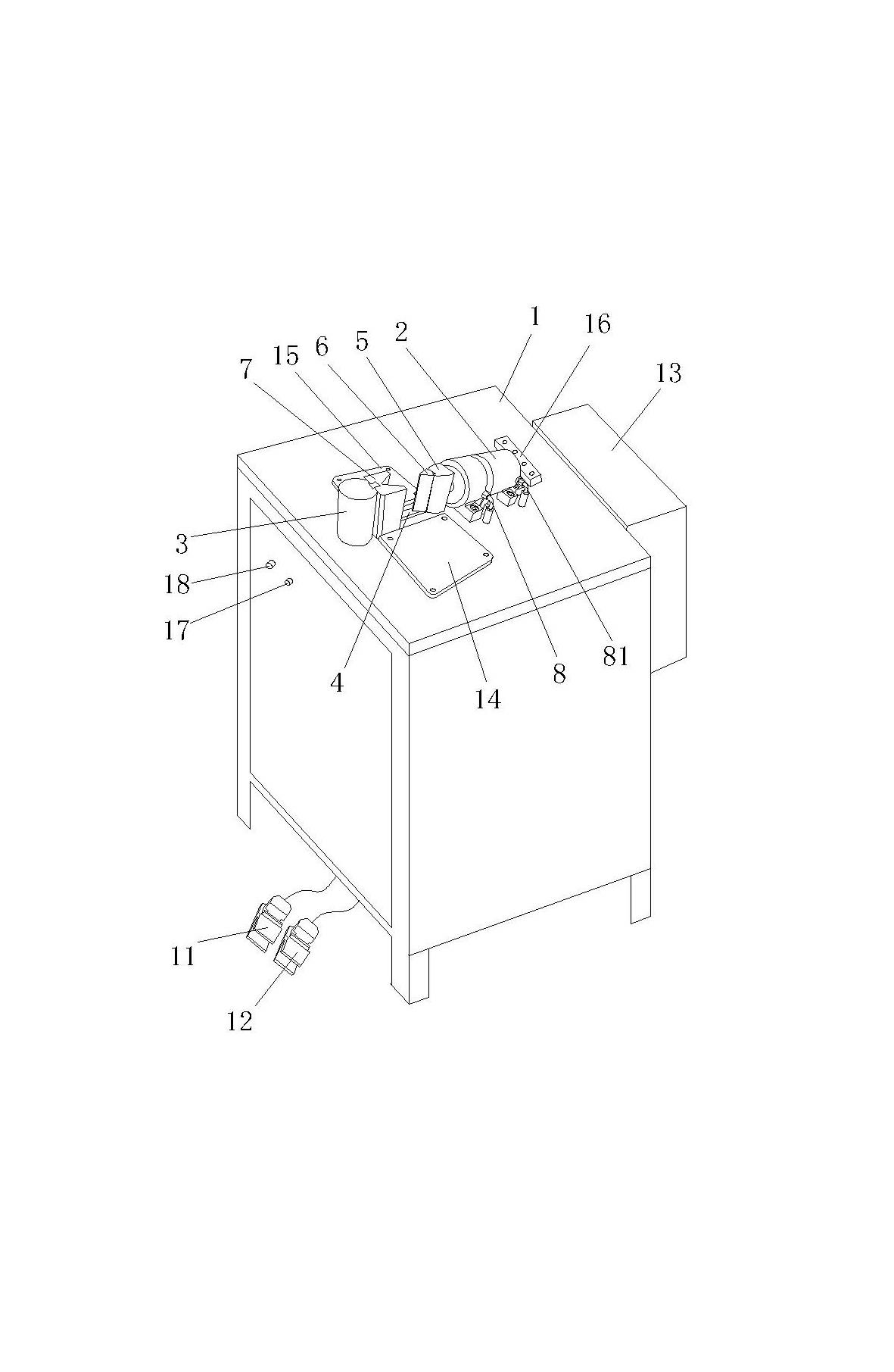
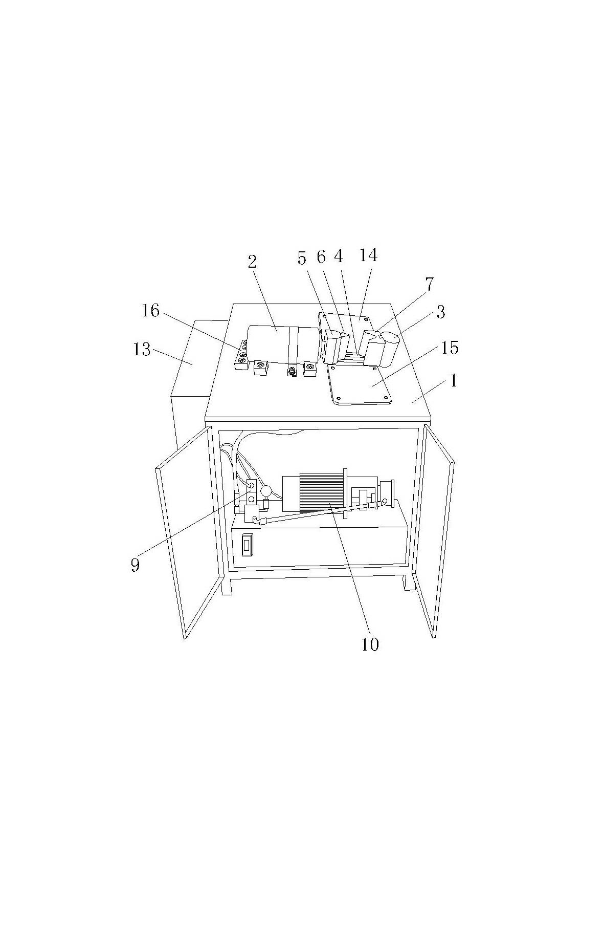
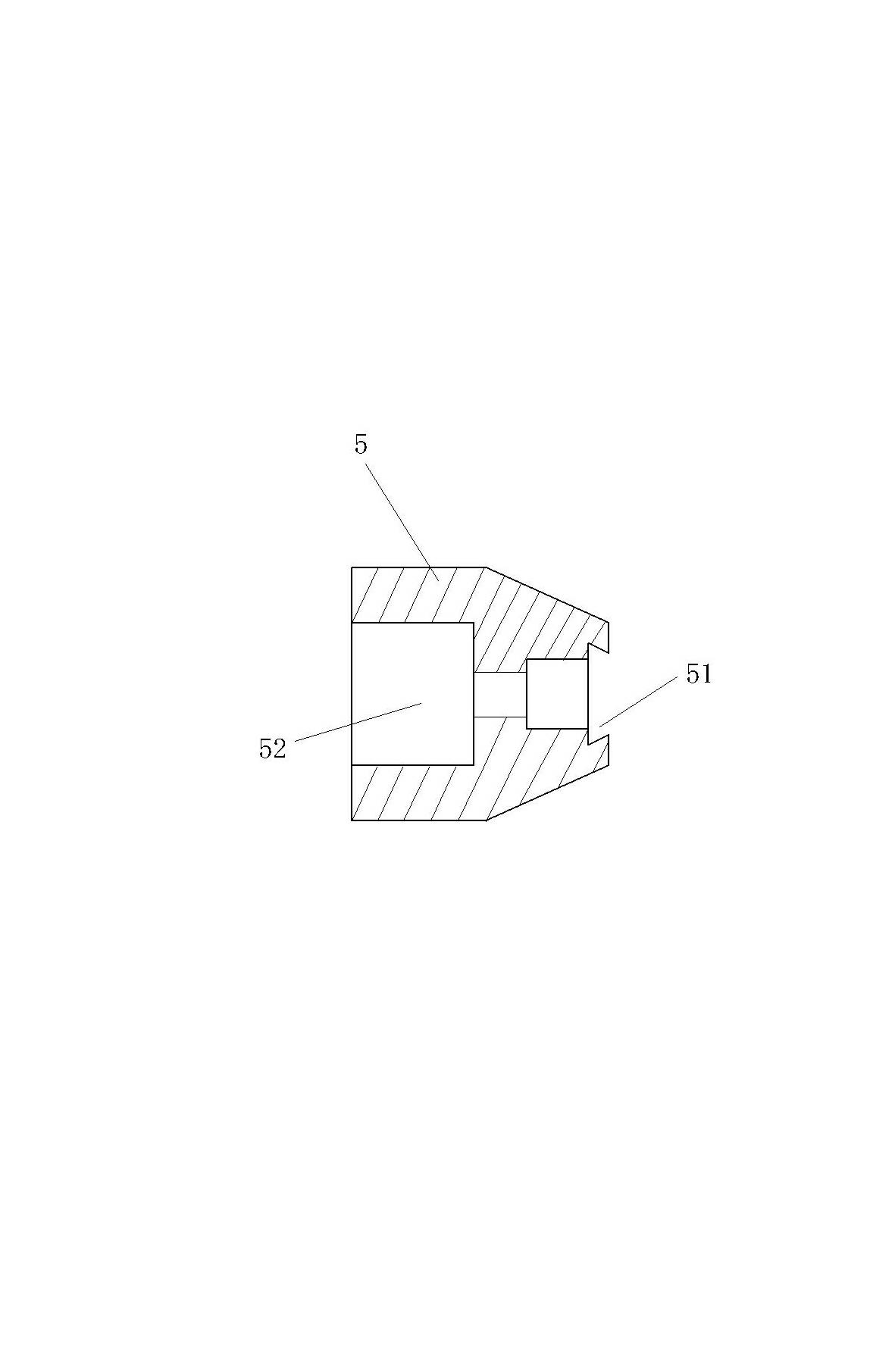
[0025] Figure 1 to Figure 6 As shown, a small horizontal bending machine includes a worktable 1 and an oil cylinder 2. A vertical column 3 is arranged on one side of the worktable 1 along the longitudinal direction, and the other side is fixed to the oil cylinder 2. The vertical column The lower part of 3 passes through the workbench 1 and forms a fixation with the workbench 1; a longitudinal track 4 is fixed on the workbench 1 between the vertical column 3 and the oil cylinder 2, and a slider 5 is fixed on the piston rod 23 of the oil cylinder 2 , the opposite sides of the slider 5 and the vertical column 3 are respectively provided with a vertical dovetail groove 51, 31, the slider 5 is fixed with the piston rod 23 of the oil cylinder 2 through the stepped hole 52 in the middle, and the dovetail groove of the slider 5 51 is equipp...


PUM


Abstract

The invention discloses a small horizontal bending machine, which comprises a working table and an oil cylinder. A vertical column is longitudinally arranged along one side of the working table, the oil cylinder is fixed on the other side of the working table, and the lower portion of the vertical column penetrates through the working table and is fixed to the working table. A longitudinal rail is fixed on the working table between the vertical column and the oil cylinder, a slider is fixed on a piston rod of the oil cylinder, opposite sides of the slider and the vertical column are respectively provided with a vertical dovetail groove, a male die is mounted on the dovetail groove of the slider, a female die is mounted on the dovetail groove of the vertical column, the lower portion of the slider is provided with a groove matched with the longitudinal rail, and the slider can move front and back along the longitudinal rail. The lateral face of the oil cylinder is connected with a hydraulic station by electromagnetic reversing valves through two oil pipes, two pedal switches are connected with electromagnetic coils of the electromagnetic reversing valves through an electric control box, and the piston rod of the oil cylinder moves ahead or back when the two pedal switches are respectively switched on. The small horizontal bending machine is simple in structure, low in manufacturing cost, convenient in disassembly and assembly and suitable for bending elongated plates.

Description

technical field [0001] The invention relates to a forging machine, especially a small horizontal bending machine. Background technique [0002] Bending machines are generally divided into manual bending machines, hydraulic bending machines and CNC bending machines. Although the manual bending machine is small in size and simple in structure, the labor intensity of the operator is high and the work efficiency is low. However, the existing hydraulic bending machine and CNC bending machine are large in size, complex in structure, and difficult to replace the mold. , the manufacturing cost of the equipment is relatively high; on September 13, 2006, an invention patent with the patent number ZL200520087121.0 and the name "Simple Plate Bending Machine" was published, which includes a gantry frame, and a There is a die suitable for the bending angle of the plate, and a punch that can move up and down along the gantry column and corresponds to the die. The two ends of the upper par...

Claims


Application Information

Patent Timeline
Patent Type & Authority Applications(China)
IPC IPC(8): B21D5/06F15B15/14F15B15/20
Inventor 张群林淡刘建波吴文福
Owner SUCTRN TECH
Why Eureka
Try Eureka