Soft tent

A technology of software and tarpaulin, applied in the field of soft tents, to achieve the effect of simple and quick implementation and convenient use

Pending Publication Date: 2018-11-20
DONGGUAN LONMAN AUTO & CAMPING ACCESSORIES MFG
0 Cites 0 Cited by

AI-Extracted Technical Summary

Problems solved by technology

[0002] With the improvement of people's life, people have higher and higher requirements for the quality of life. At present, many tourist enthusiasts drive open-top jeeps in the wild, such...

Method used

[0045] Various tarpaulins are connected by connecting member...

Abstract

The invention relates to a soft tent. The soft tent comprises supporting skeletons, two horizontal supporting frames, a rotatable supporting frame, a tent cloth assembly and two U-shaped rods. Fixingparts are arranged at the lower ends of the supporting skeletons, lateral cracks are arranged on the front sides of the supporting skeletons, and fixed platforms are arranged at the upper ends of thesupporting skeletons; the two horizontal supporting frames are connected to the upper portions of the supporting skeletons on the two sides respectively and comprise fixing plates, lateral connectingplates are arranged on the outer side faces of the fixing plates, L-shaped plates are connected to the outer sides of the lateral connecting plates, and upper cracks are formed between the L-shaped plates and the lateral connecting plates; the rotatable supporting frame comprises a connecting plate, supporting rods are connected to the two sides of the connecting plate respectively, the lateral connecting plates extend toward to the inner sides to form fixing bottom plates, and supporting pieces are arranged on the fixing bottom plates; the supporting pieces and the lower ends of the supporting rods are pivoted; the tent cloth assembly comprises two pieces of lateral tent cloth, a rear tent cloth piece and a top tent cloth piece; the U-shaped rods are used for supporting the tent cloth assembly. Through the supporting skeletons, the horizontal supporting frames and others, the soft tent can be rapidly fixed to an open car body, implementation is easy, rapid and convenient, and using isconvenient.

Application Domain

Technology Topic

Image

  • Soft tent
  • Soft tent
  • Soft tent

Examples

  • Experimental program(1)

Example Embodiment

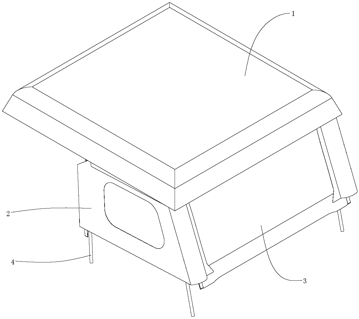
[0024] Embodiment: a soft top for a convertible, comprising:
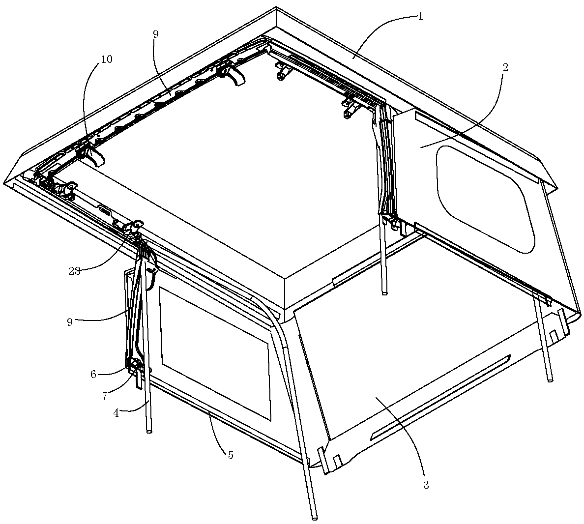
[0025] The supporting frame 9 located on both sides, the lower end of the supporting frame 9 is provided with a fixing part 6 for fixing to the vehicle body, the front side of the supporting frame 9 is provided with a side gap 30 for connecting the side tarpaulin 2, the supporting frame 9 The upper end is provided with a fixed platform 15;
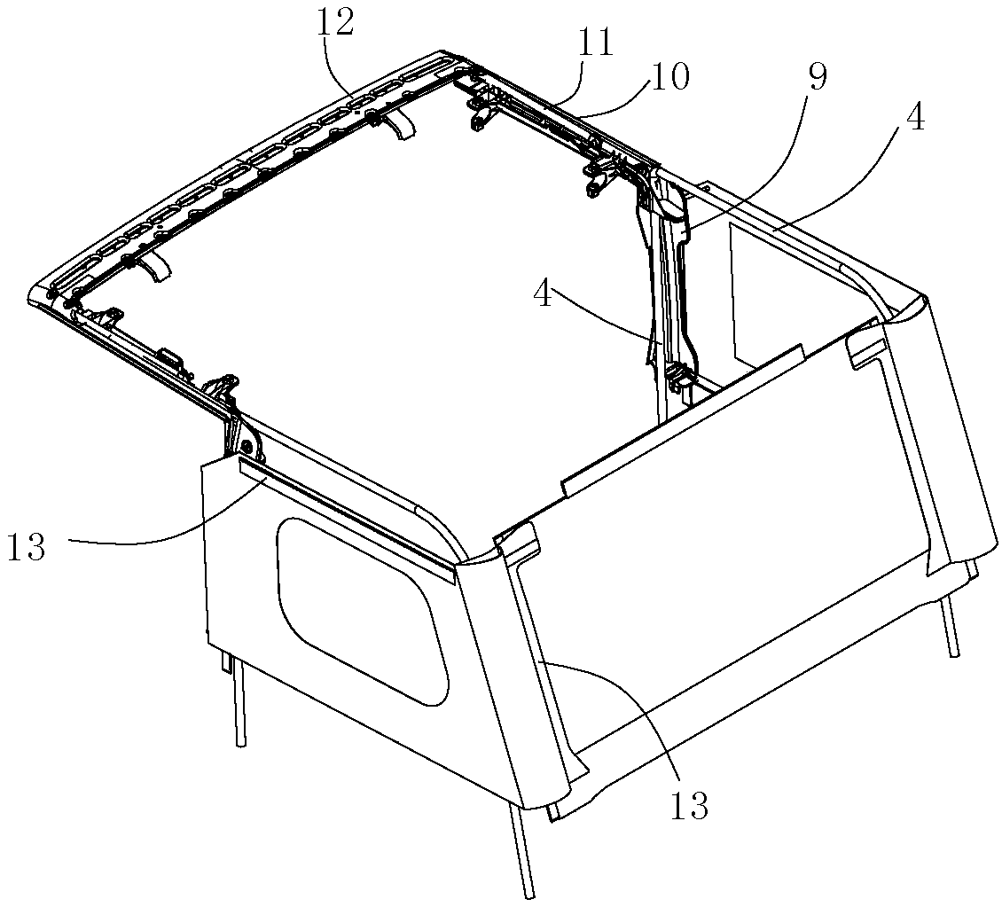
[0026] Two horizontal support frames 10 are respectively connected above the support frames 9 on both sides; the horizontal support frame 10 includes a fixed plate 20 connected to the fixed platform 15, and the outer side of the fixed plate 20 is provided with a side connecting plate 8, and the An L-shaped plate is connected to the outer side of the side connecting plate 8, and an upper gap 22 for fixing the roof cloth is formed between the L-shaped plate and the side connecting plate 8;
[0027] The rotating support frame includes a connecting plate 12 located in the middle, and the two sides of the connecting plate 12 are respectively connected with supporting rods 11, and the lower end of the side connecting plate 8 extends inwardly to a fixed bottom plate 29, and the middle part of the fixed bottom plate 29 is provided with a supporting piece 24 ; The upper end of the supporting piece 24 is pivotally connected with the lower end of the corresponding supporting rod 11; when specifically set, the upper end of the supporting piece 24 is provided with a shaft hole 25, which is pivotally connected with the supporting rod 11 through a pin.
[0028] The tarpaulin assembly includes two side tarpaulins 2, a rear tarpaulin 3 and a top tarpaulin 1; the rear tarpaulin 3 is connected between the two side tarpaulins, and the rear end of the top tarpaulin 1 is connected to the rear tarpaulin. The upper end of 3 is connected, the side of top tarpaulin 1 is connected with side tarpaulin 2 and horizontal support respectively; the front end of tarpaulin is connected with connecting plate 12;
[0029] The lower end of the side tarpaulin 2 is provided with an inwardly turned connecting strip, and the connecting strip is connected with a connecting block 5 for fixing with the car body. The connecting block 5 is arranged in an inverted U shape, and the connecting bar is inserted into the connecting block 5; When setting, the lower end of the rear tarpaulin 3 is also provided with a connecting strip and connected with a connecting block 5 .
[0030] Two U-shaped bars 4 are located on both sides respectively. The U-shaped bar 4 includes two vertical sections and a transverse section, wherein one vertical section is connected with the support frame 9, and the other vertical section is connected with the end of the side tarpaulin 2 portion, and the transverse section is offset against the top tarpaulin 1.
[0031] This technical scheme is fixed on the both side edges of the convertible by designing the support frame 9, the side gap 30 of the support frame 9 clamps the front side of the side tarpaulin 2, and the horizontal support frame 10 passes through the fixing plate 20 and the support frame 9. The fixed platform 15 is connected, and the lower end of the side tarpaulin 2 is fixed on the car body through the connection of the connecting strip and the connecting block 5; the two sides of the rear tarpaulin 3 are respectively connected with the rear ends of the side tarpaulins 2 on both sides; The rod 4 assists in unfolding the side tarpaulin 2 and the rear tarpaulin 3, and supports the top tarpaulin 1. The rear end of the top tarpaulin 1 is connected with the upper end of the rear tarpaulin 3. The upper end of the tarpaulin 2 is connected, and the front end and both sides of the front end of the top tarpaulin 1 are respectively connected with the connecting plate 12 of the rotating support frame and the horizontal support frame 10 . The overlapping of tarpaulin components is simple and quick.
[0032] Further, see Figure 4 , the inner side of the fixed platform 15 is provided with an auxiliary fixing piece 17, the auxiliary fixing piece 17 is provided with a connecting hole 18, the horizontal support 10 is provided with a hollow fixing column 21, and the auxiliary fixing piece 17 is connected with the hollow fixing column 21 by a fixing bolt 23.
[0033] Through the connection of the auxiliary fixing piece 17 and the hollow fixing column 21 , the connection of the horizontal support 10 and the support frame 9 is assisted.
[0034] Furthermore, the fixing platform 15 is provided with an insertion hole 16 , and the fixing plate 20 is provided with an insertion block 19 matching with the insertion hole 16 , and the insertion block 19 is inserted into the insertion hole 16 .
[0035] The cooperation between the socket 16 and the insert block 19 can play a role of positioning, and also assist in the fixed connection of the fixing plate 20 and the fixing platform 15 .
[0036] Further, the horizontal support frame 10 is provided with two connecting claws 28 , and a side connecting piece 27 is arranged between the two connecting claws 28 , and the side connecting piece 27 is provided with a side connecting hole 26 .
[0037] The side connecting pieces 27 and the side connecting holes 26 are provided, so that the crossbeams can be connected between the side connections 26 on both sides, and the roof cloth 1 is supported by the crossbeams.
[0038] Further, the fixing part 6 is provided with several connecting claws 7 , and a concave hole 14 matching the vertical section of the U-shaped bar 4 is formed between two connecting claws 7 .
[0039] The connecting claw 7 can be conveniently connected with the claw of the car body; it is also convenient to be used for rope binding; secondly, the recessed hole 14 is set, which can facilitate the fixing of the U-shaped bar,
[0040] Further, several connecting claws 28 extend from the inner side of the horizontal support frame 10 .
[0041] The inner side of the horizontal support frame 10 is provided with connecting claws 28 , which can assist in connecting the horizontal bars for supporting the top tarpaulin 1 .
[0042] Further, the connection plate 12 is connected with a connection buckle.
[0043] After the connecting buckle is set, it can assist to connect the connecting plate 12 with the vehicle body.
[0044] Further, the top tarpaulin 1 is respectively connected with the side tarpaulin 2 and the rear tarpaulin 3 through the connector 13, and the rear tarpaulin 3 is also connected with the side tarpaulin 2 through the connector 13; the connector 13 includes a zipper, snap button or magic paste.
[0045] Various tarpaulins are connected by setting the connecting piece 13, so that the tarpaulins are convenient to be disassembled.

PUM

no PUM

Description & Claims & Application Information

We can also present the details of the Description, Claims and Application information to help users get a comprehensive understanding of the technical details of the patent, such as background art, summary of invention, brief description of drawings, description of embodiments, and other original content. On the other hand, users can also determine the specific scope of protection of the technology through the list of claims; as well as understand the changes in the life cycle of the technology with the presentation of the patent timeline. Login to view more.

Similar technology patents

Coke oven checker brick mounting device and construction method therefor

ActiveCN110144231ASimple and quick to implementImprove work efficiencyCoke oven brickworkEngineeringCoke oven
Owner:CHINA FIRST METALLURGICAL GROUP

Improved control device for adding CFB power plant bed materials

PendingCN111006208ARealize the use of size screeningSimple and quick to implementFluidized bed combustionApparatus for fluidised bed combustionSlagPlant
Owner:SHANXI HEPO POWER GENERATION CO LTD

A bus protection method for CTs connected at two sides of a bus-tie switch

ActiveCN110661235ASimple and quick to implementConducive to on-site promotion and applicationEmergency protective arrangements for automatic disconnectionEmbedded systemThree-phase electric power
Owner:长园深瑞继保自动化有限公司

Classification and recommendation of technical efficacy words

  • Easy to use
  • Simple and quick to implement

Laser assisted total joint arthroplasty

InactiveUS20090234360A1Easy to useNon-surgical orthopedic devicesSurgical sawsLaser assistedLaser guidance
Owner:ALEXANDER VLADIMIR

System, method, and apparatus for settlement for participation in an electric power grid

ActiveUS8583520B1Communication securityEasy to useLevel controlCoin-freed apparatusNetwork managementGrid operator
Owner:CAUSAM ENERGY INC

A bus protection method for CTs connected at two sides of a bus-tie switch

ActiveCN110661235ASimple and quick to implementConducive to on-site promotion and applicationEmergency protective arrangements for automatic disconnectionEmbedded systemThree-phase electric power
Owner:长园深瑞继保自动化有限公司

Improved control device for adding CFB power plant bed materials

PendingCN111006208ARealize the use of size screeningSimple and quick to implementFluidized bed combustionApparatus for fluidised bed combustionSlagPlant
Owner:SHANXI HEPO POWER GENERATION CO LTD

Coke oven checker brick mounting device and construction method therefor

ActiveCN110144231ASimple and quick to implementImprove work efficiencyCoke oven brickworkEngineeringCoke oven
Owner:CHINA FIRST METALLURGICAL GROUP
Why Eureka
Try Eureka