Method for position indexing of a machine or similar on the floor and machine leg used therefor

a technology of position indexing and machine or similar, which is applied in the direction of machine supports, mechanical equipment, manufacturing tools, etc., can solve the problems of inconvenient installation the inability to access the soleplate, and the inability to adjust the position of the machine leg,

Inactive Publication Date: 2007-05-17
ABB MC
View PDF5 Cites 2 Cited by
  • Summary
  • Abstract
  • Description
  • Claims
  • Application Information

AI Technical Summary

Benefits of technology

[0015] The method of the invention is very simple and quick to implement (one hole drilled per leg), and is does not require the machine to be handled in any way other than being put into its final position.

Problems solved by technology

Such a machine leg presents the drawback of requiring access to the soleplate in order to be able to be secured thereto.
However, these projecting portions constitute obstacles preventing the stands of adjacent machines being disposed contiguously.
That type of installation procedure is lengthy and complex to implement and requires a large amount of handling of the machine by means of hoists of large dimensions adapted to the weight and the size of the machine.
Nevertheless those numerous passages complicate the design of the machine and weaken it.
That method is made difficult to implement by the fact that the fastener screws must be put into position blind in the bottoms of passages that may be of considerable length.

Method used


Image

  • Method for position indexing of a machine or similar on the floor and machine leg used therefor
  • Method for position indexing of a machine or similar on the floor and machine leg used therefor

Examples


Embodiment Construction

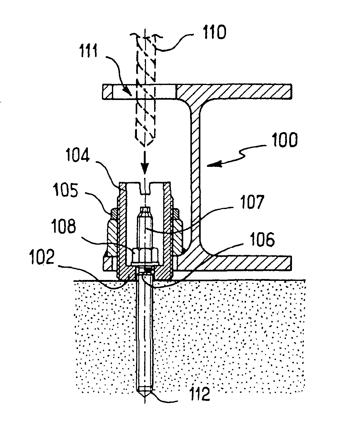
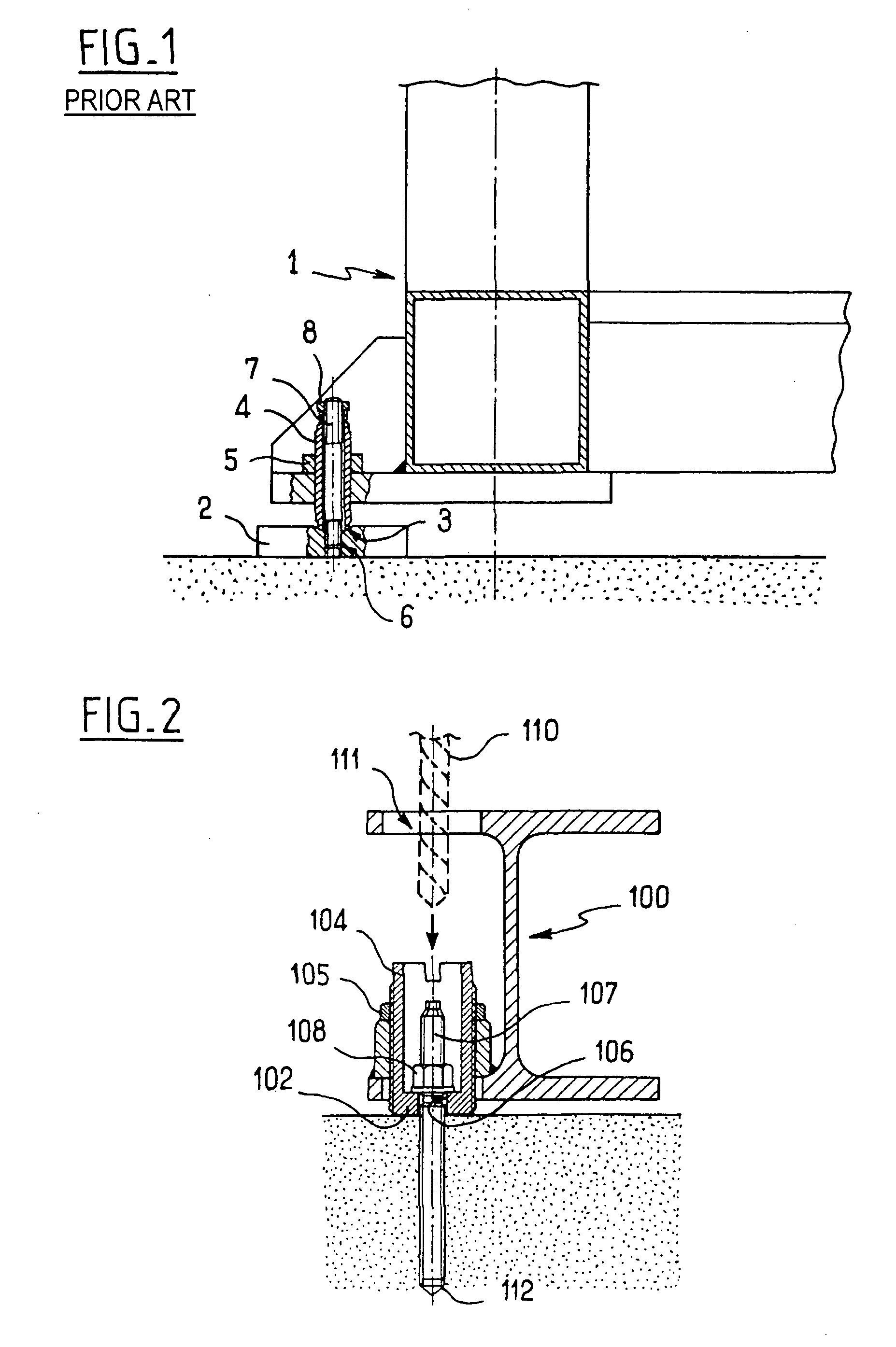
[0022] In FIG. 2, the machine 100 includes a stand, with a portion of its structure being visible in the form of an I beam. The stand is fitted with legs such as the leg shown, each comprising a bushing 104 screwed on the bottom flange of the I beam. The bushing 104 has a bottom end presenting a bottom 102 made integrally with the bushing and bearing directly on the ground. The bottom 102 forms a soleplate that is integral with bushing, thus making a saving of one part and avoiding any risk of the soleplate becoming lost or wrongly positioned relative to the bushing while the machine is being put into place. In a variant, the bottom need not be integral with the bushing, but could be fitted thereto so as to be intimately secured therewith, e.g. by means of adhesive or welding. The bottom includes a central orifice 106 opening out into the bushing 104.

[0023] The machine 100 provided with its legs is initially put into place on the ground in the desired final position. Once the machi...


PUM

PropertyMeasurementUnit
pressureaaaaaaaaaa
weightaaaaaaaaaa
sizeaaaaaaaaaa

Abstract

Method of indexing a machine or the like in position on the ground, the machine having a leg with a hollow bushing (104) for adjusting its level, which bushing is screwed to the machine and bears without sliding on a soleplate (102) in contact with the ground, the soleplate including an orifice (106) opening out into the bushing. The method includes the steps of positioning the machine on the ground, of drilling a hole (112) in the ground in line with the orifice (106) in the soleplate (102) using a drilling tool passing along the bushing (104) and through the orifice (106) in the soleplate, and of fitting in the hole a positioning member (107) that co-operates with the orifice (106) in the soleplate in order to index its position on the ground. A machine leg specially adapted to implementing the method is also disclosed.

Description

[0001] The invention relates to a method of indexing the position on the ground of a machine or the like, such as a machine tool or a welding robot, and it also relates to a machine leg used therefor. BACKGROUND OF THE INVENTION [0002] A machine leg in accordance with the prior art is shown in section in accompanying FIG. 1. [0003] The machine 1 comprises a frame with a stand that rests on the ground, generally a concrete floor, via legs such as the leg shown which includes a bushing 4 screwed to the stand of the machine and projecting beneath it. [0004] The bushing 4 has a bottom end which is received in a conical recess 3 in a soleplate 2 secured to the ground by fastener screws (not shown) and serving to distribute pressure over the ground in order to avoid indenting it. [0005] The bushing 4, once it has been screwed in or out so as to adjust the level of the machine properly, is itself locked in position on the stand on the machine 1 by means of a lock nut 5. [0006] Under the ef...

Claims


Application Information

Patent Timeline
Patent Type & Authority Applications(United States)
IPC IPC(8): B23P11/00F16M7/00
CPCY10T29/49947F16M7/00
Inventor OL, JEAN-PHILIPPEMALATIER, FRANCOIS
Owner ABB MC
Why Eureka
Try Eureka