Electronic product bracket

A technology for electronic products and vertical supports, applied in the directions of machines/supports, supporting machines, mechanical equipment, etc., can solve the problems of inconvenient placement and positioning of electronic products, and achieve the effect of simple and easy operation.

Inactive Publication Date: 2018-11-20
成都捷科菲友信息技术有限公司
View PDF0 Cites 4 Cited by
  • Summary
  • Abstract
  • Description
  • Claims
  • Application Information

AI Technical Summary

Problems solved by technology

[0004] The object of the present invention is: in order to solve the problem of inconvenient placement and positioning of existing electronic products, the present invention provides a bracket that can be adjusted in height and angle and is suitable for electronic products of different sizes

Method used


Image

  • Electronic product bracket
  • Electronic product bracket

Examples


Embodiment 1

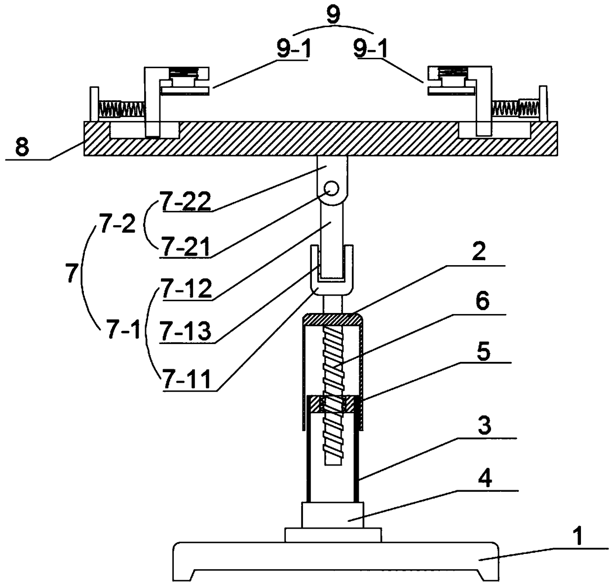
[0026] Such as figure 1 As shown, this embodiment provides a bracket for electronic products, including a base 1, on which a lift-and-retract rod assembly is provided. 3 outer circumference, one end of the bottom rod 3 is fixedly connected with the rotary knob 4, and the inner fixed sleeve of the port at the other end of the bottom rod 3 is provided with a drive nut 5, the outer wall of the drive nut 5 is fixedly connected with the inner wall of the bottom rod 3, and the inner wall of the drive nut 5 The screw rod 6 is sleeved, and the vertically upward end of the screw rod 6 is fixedly connected with the inner top wall of the sleeve rod 2, and the end of the rotary knob 4 away from the bottom rod 3 is rotationally connected with the base 1, and the top of the sleeve rod 2 is connected with an angle adjustment Component 7, the top of the angle adjustment component 7 is connected with a placement plate 8, and the placement plate 8 is provided with an elastic positioning compone...

Embodiment 2

[0031] Such as figure 1 As shown, the present embodiment is further optimized on the basis of embodiment 1, specifically:

[0032] The angle adjustment assembly 7 includes a front and rear angle adjustment assembly 7-1 and a left and right angle adjustment assembly 7-2. The front and rear angle adjustment assembly 7-1 includes a first connecting rod 7-11 and a second connecting rod 7-12. One end of a connecting rod 7-11 is fixedly connected to the top of the sleeve rod 2, and the other end is connected to the second connecting rod 7-12 through the first damping shaft 7-13, and the second connecting rod 7-12 is far away from the first connecting rod 7 One end of -11 is connected with the left and right angle adjustment assembly 7-2. The left and right angle adjustment assembly 7-2 includes a second damping shaft 7-21 and a third connecting member 7-22, the second connecting rod 7-12 is connected to the third connecting member 7-22 through the second damping shaft 7-21 , the s...


PUM


Abstract

The invention discloses an electronic product bracket and relates to the technical field of electronic products. The electronic product bracket comprises a base, wherein a telescopic rod assembly is arranged on the base and comprises a loop bar and a bottom rod; the loop bar is arranged on the periphery of the bottom rod in a sleeving manner; a rotary button is fixedly connected with one end of the bottom rod; the other end of the bottom rod is fixedly connected with a driving nut; a screw rod is arranged in the driving nut in a sleeving manner; the vertically upward end of the screw rod is fixedly connected with the top wall of the loop bar; the end, far away from the bottom rod, of the rotary button is rotatably connected with the base; an angle adjusting assembly is connected with the top of the loop bar; a placement plate is connected with the top of the angle adjusting assembly; and an elastic positioning assembly for positioning electronic products with different sizes is arranegd on the placement plate. The electronic product bracket can simply and flexibly adjust the height and the angle to meet different height and angle adjusting demands of different using environments, and is simple to operate and high in applicability.

Description

technical field [0001] The present invention relates to the technical field of electronic products, and more specifically relates to a support for electronic products. Background technique [0002] With the development of electronic products in the direction of high performance, low consumption, high precision, high stability, and intelligence, various electronic products are popularized in people's lives, especially tablet notebook computers and large-screen smart phones, which have occupied the More and more life, leisure and entertainment time, people use tablets or mobile phones to watch movies, surf the Internet, socialize, etc. Therefore, electronic products bring great convenience to people's lives. [0003] However, there are also disadvantages in using electronic products for a long time. For example, holding them for a long time may easily cause wrist fatigue, and it is not convenient to free hands. Cervical spine, eyesight and other damage. Contents of the inve...

Claims


Application Information

Patent Timeline
Patent Type & Authority Applications(China)
IPC IPC(8): F16M11/28F16M11/16
CPCF16M11/16F16M11/28
Inventor 苏小刚
Owner 成都捷科菲友信息技术有限公司
Why Eureka
Try Eureka