
Carrier tape for electronic components

A technology of electronic components and carrying, applied in the direction of electrical components, electrical components, packaging, etc., can solve the problems of unfavorable installation efficiency of electronic components, unable to increase the speed of tearing and peeling cover tapes, etc., to prevent pollution and bending, and have good installation and operation capabilities , The effect of preventing misidentification and misoperation

Inactive Publication Date: 2002-07-31
SUMITOMO BAKELITE CO LTD
View PDF1 Cites 0 Cited by
  • Summary
  • Abstract
  • Description
  • Claims
  • Application Information

AI Technical Summary

Problems solved by technology

Therefore, the speed of peeling off the cover tape cannot be increased, and the cover tape may be damaged or the carrier tape 1 may be subjected to vibrations on the surface mount equipment.
This is not good for improving the installation efficiency of electronic components

Method used


Image

  • Carrier tape for electronic components
  • Carrier tape for electronic components
  • Carrier tape for electronic components

Examples


example 1

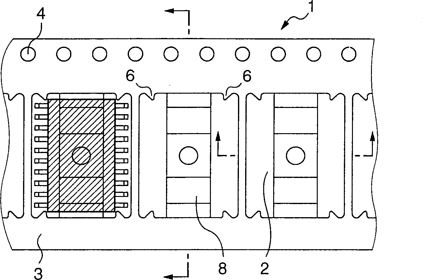
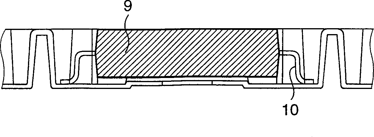
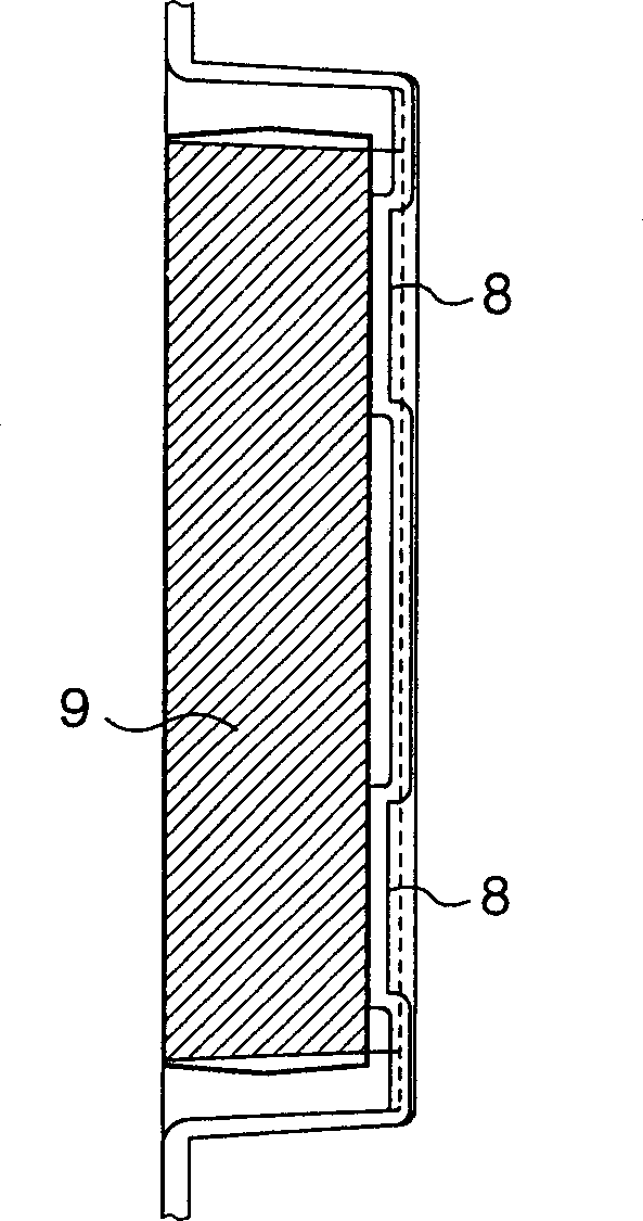
[0033] Figure 1-3 Shown is a carrier tape 1 in which a convex portion 2 is formed so that a plurality of IC packages such as SOP (Small Outline Package), SSOP (Shrink Small Outline Package), TSOP (Thin Small Outline Package), TSSOP (Thin Shrink Small Outline Package) Plug-in) and PLCC (Plastic Lead Sealed Chip Carrier) are stored in it. In the carrier belt 1, two protruding portions A: 6 are formed on the first side wall and the third side wall of the lower convex portion 2 in the longitudinal direction of the belt, in the middle of each side wall of the lower convex portion 2, Whereas two central protrusions 8 are formed on the bottom of the convex portion 2 in a direction perpendicular to the longitudinal direction of the belt.

[0034] Such as Figure 4As shown, the distance A-A between a pair of protruding parts A: 6 is preferably 0.05-0.5mm larger than the length of the electronic component in the longitudinal direction of the tape, measured at the position where the d...

example 2

[0041] The carrier tape in this example is the same as in Example 1, except that Figure 5-7 As shown, two protruding parts B: 7 are formed between protruding parts A: 6, and protruding parts A: 6 are arranged on the first and third side walls of the lower convex part 2, which are all in the longitudinal direction of the belt Located in the middle of some side walls of the lower convex part 2. The protruding portions B: 7 do not protrude beyond the protruding portions A: 6 in a direction perpendicular to the longitudinal direction of the carrier tape, and these protruding portions B: 7 are formed so as to prevent the main body end face of the electronic component 9 from vibrating in its longitudinal direction .

[0042] Preferably, the shortest distance (B) between the two protruding portions B: 7 in the direction perpendicular to the longitudinal direction of the carrier tape is 0.1-1 mm larger than the length (E) of the electronic component in the direction perpendicular to...


PUM

PropertyMeasurementUnit
Lengthaaaaaaaaaa

Abstract

The present invention provides a carrier tape for electronic components comprising a flexible tape material having embossed portions for storing electronic components at regular intervals in the lengthwise direction of the tape, characterized in that each of the opposing first and third side walls of the embossed portion which are positioned at both sides of the lengthwise direction of the tape, has a pair of first protrusions A for preventing the electronic component from transverse shaking which protrude inwardly in the embossed portion, and optionally further has, between the protrusions A, a plurality of second protrusions B for preventing the electronic component from longitudinal shaking which differ in shape from the protrusions A. The carrier tape has, at the bottom surface of the embossed portion, two or more central protuberances in the direction perpendicular to the lengthwise direction of the carrier tape.

Description

technical field [0001] The present invention relates to a product for packaging and carrying components, and more particularly to an electronic component carrier tape for packaging and carrying electronic components such as ICs. Background technique [0002] So far, as Figure 9 The carrier belt shown is such a belt. The carrier tape 1 is made of a flexible resin material, and includes two parts of a concave portion 2 (hereinafter referred to as “convex portion 2 ”) and a flange portion 3 . A plurality of convex portions 2 are distributed at equal intervals along the length direction of the carrier tape 1 (along the longitudinal direction of the tape), and are used to store related electronic components in each convex portion. The flange portion 3 is used to allow a tape-shaped covering (hereinafter referred to as "cover tape") to be adhered thereon so that the stored electronic components will not fall out of the opening of the lower convex portion during the transportatio...

Claims


Application Information

Patent Timeline
IPC IPC(8): H05K13/04
CPCH05K13/0417H05K13/0084B65D73/02H05K13/021
Inventor 三上真一
Owner SUMITOMO BAKELITE CO LTD
Learn More