Pump body assembly, fluid machine and heat-exchanging equipment

A component and pump body technology, applied in mechanical equipment, pump components, liquid fuel engines, etc., can solve the problems of easy eccentric rotation of the piston sleeve, affecting the working efficiency of the pump body components, etc., to improve the operation reliability and performance. Effect

Pending Publication Date: 2018-11-23
GREE ELECTRIC APPLIANCES INC
View PDF0 Cites 3 Cited by
  • Summary
  • Abstract
  • Description
  • Claims
  • Application Information

AI Technical Summary

Problems solved by technology

[0003] The main purpose of the present invention is to provide a pump body assembly, fluid machinery and heat exchange equipment to solve the problem in

Method used


Image

  • Pump body assembly, fluid machine and heat-exchanging equipment
  • Pump body assembly, fluid machine and heat-exchanging equipment
  • Pump body assembly, fluid machine and heat-exchanging equipment

Examples


Embodiment 1

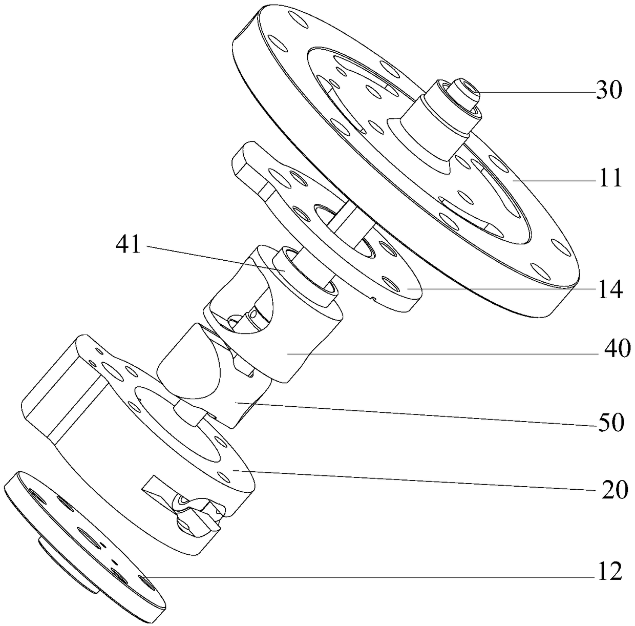
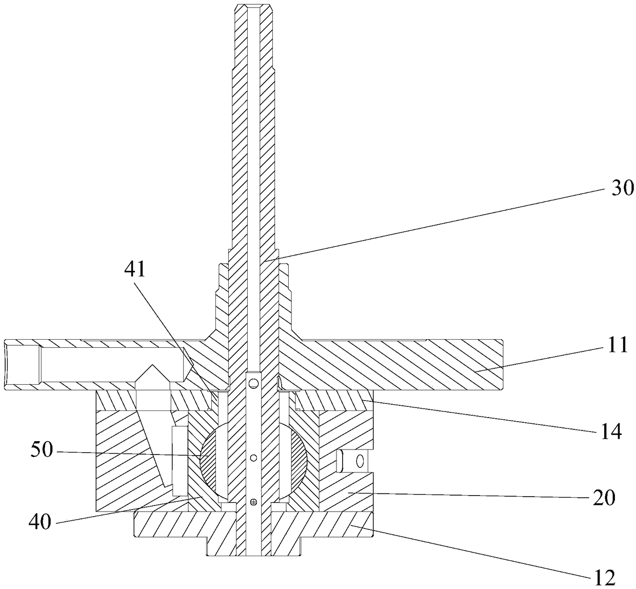
[0069] Such as figure 1 and figure 2 As shown, the pump body assembly includes an upper flange 11, an upper limit plate 14, a cylinder 20 and a piston assembly. Wherein, the upper limit plate 14 is located between the upper flange 11 and the cylinder 20 . The piston assembly is arranged in the cylinder 20. The piston assembly includes a piston sleeve 40 and a piston 50 slidably arranged in the piston sleeve 40. The upper end surface of the piston sleeve 40 and the lower end surface of the upper limit plate 14 are spaced to prevent the piston sleeve from 40 is displaced in the radial direction relative to the upper flange 11 .

[0070] Applying the technical solution of this embodiment, during the operation of the pump body assembly, the upper end of the piston sleeve 40 is limited and supported by the upper limit plate 14, thereby preventing the piston sleeve 40 from moving in the radial direction during operation, ensuring that the piston The sleeve 40 can rotate normally...

Embodiment 2

[0081] The difference between the pump body assembly in the second embodiment and the first embodiment is that the structure of the upper limit plate 14 is different.

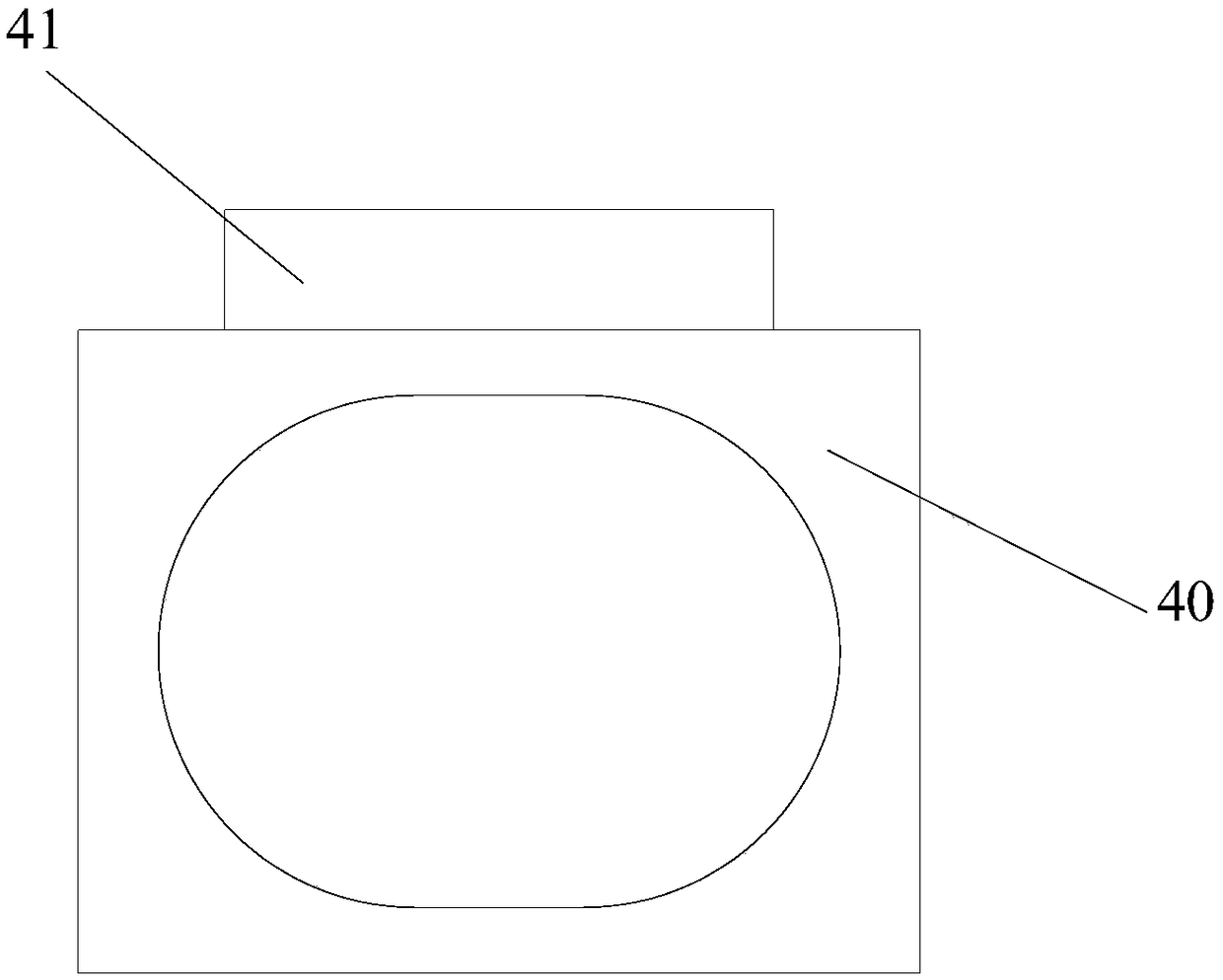
[0082] Such as Figure 5 to Figure 9 As shown, the surface of the upper limit plate 14 facing the piston sleeve 40 has a fourth limit groove 141, the upper end surface of the piston sleeve 40 has a first extension 41, and the first extension 41 extends into the fourth limit groove 141 And stop with the fourth limiting groove 141 . Specifically, during the operation of the pump body assembly, the first extension part 41 protrudes into the fourth limiting groove 141 of the piston sleeve 40 and stops with the fourth limiting groove 141, thereby realizing the upper limit plate 14 Limiting and supporting the upper end of the piston sleeve 40 prevents structural interference between the piston sleeve 40 and the piston 50 or the cylinder 20 to affect the normal operation of the pump body assembly. The above structur...

Embodiment 3

[0085] The difference between the pump body assembly in the third embodiment and the first embodiment is that the structure of the upper limit plate 14 is different

[0086] Such as Figure 10 to Figure 13 As shown, the surface of the upper limit plate 14 facing the piston sleeve 40 has a third extension portion 142 , and the third extension portion 142 protrudes into the piston sleeve 40 and makes a limit stop with the inner surface of the piston sleeve 40 . In this way, the third extension portion 142 of the upper limit plate 14 extends into the piston sleeve 40 and stops the upper end of the piston sleeve 40 so as to limit the radial direction of the piston sleeve 40 by the upper limit plate 14 .

[0087] In other embodiments not shown in the accompanying drawings, there is a stepped surface on the inner surface of the piston sleeve, and the stepped surface is located at the end of the piston sleeve facing the upper flange, and the third extension part extends into the step...


PUM


Abstract

The invention provides a pump body assembly, a fluid machine and heat-exchanging equipment. The pump body assembly comprises an upper flange, an upper limiting board, a cylinder and a piston assembly,wherein the upper limiting board is positioned between the upper flange and the cylinder; the piston assembly is arranged in the cylinder; the piston assembly comprises a piston bush and a piston which is arranged in the piston bush in a slide manner; the upper end face of the piston bush is matched with the lower end face of the upper limiting board in a limiting manner in order to prevent the piston bush from moving in a radial direction relative to the upper flange. By adopting the pump body assembly, the problem of influence on the working efficiency of the pump body assembly since the piston bush is liable to rotate eccentrically in the prior art is solved effectively.

Description

technical field [0001] The invention relates to the technical field of pump body components, in particular to a pump body component, fluid machinery and heat exchange equipment. Background technique [0002] At present, during the operation of the pump body assembly, the piston sleeve is prone to eccentricity and tilt rotation, which causes the piston sleeve to easily rub against the cylinder and the piston, seriously affecting the working efficiency and performance of the pump body assembly. Contents of the invention [0003] The main purpose of the present invention is to provide a pump body assembly, fluid machinery and heat exchange equipment to solve the problem in the prior art that the piston sleeve of the pump body assembly is prone to eccentric rotation and affects the working efficiency of the pump body assembly. [0004] In order to achieve the above object, according to one aspect of the present invention, a pump body assembly is provided, including: an upper f...

Claims


Application Information

Patent Timeline
IPC IPC(8): F04C18/00F04C29/00
CPCF04C18/00F04C29/00F04C2240/80F04C2240/20F04C2240/10F04C2240/60
Inventor 杨森尚文海马利亚杜忠诚李直张金圈许甲岿郭霜
Owner GREE ELECTRIC APPLIANCES INC
Why Eureka
Try Eureka