
Handheld infrared flaw detector and detection method thereof

An infrared flaw detection, hand-held technology, applied in the field of defect detection, can solve the problems of large volume, inconvenience to carry, and the overall weight of the equipment, and achieve the effects of easy portability, weight reduction, and convenience for calling

Pending Publication Date: 2018-11-23
中新红外科技(武汉)有限公司
View PDF0 Cites 4 Cited by
  • Summary
  • Abstract
  • Description
  • Claims
  • Application Information

AI Technical Summary

Problems solved by technology

[0003] However, most of the thermal imaging detection technologies in the prior art use high-power flashlights. Although the flashlights are more convenient to use, they are large in size, heavy in overall weight, and inconvenient to carry.

Method used


Image

  • Handheld infrared flaw detector and detection method thereof
  • Handheld infrared flaw detector and detection method thereof
  • Handheld infrared flaw detector and detection method thereof

Examples


Embodiment 3

[0045] Embodiment 3 of the present invention is a handheld infrared flaw detector. On the basis of Embodiment 2, asbestos, thermal nylon, PEEK, etc. can be selected as the heat insulating material 4 .

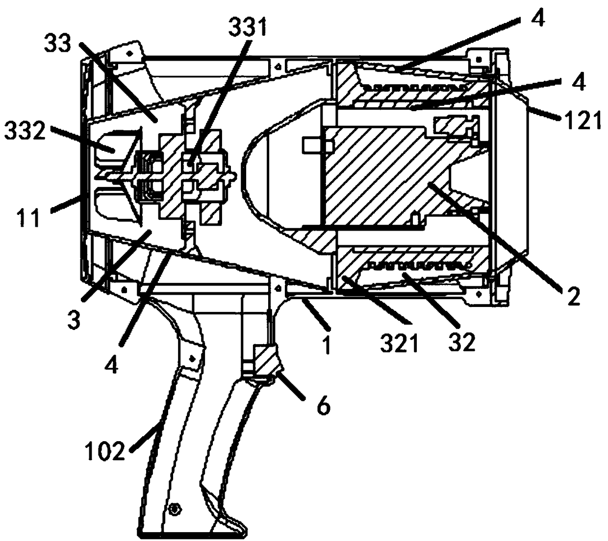
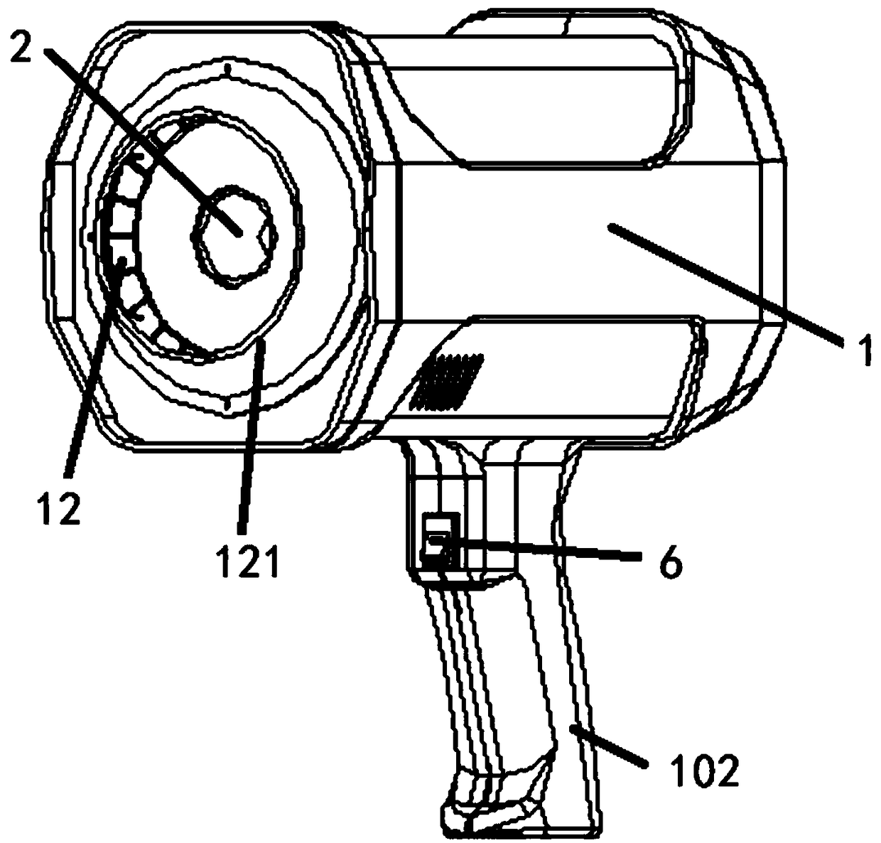
[0046] like figure 1 As shown, Embodiment 4 of the present invention is a handheld infrared flaw detector. On the basis of Embodiment 1, the air supply member 33 is a fan, and the fan includes a motor 331 and a fan blade 332. The motor 331 is fixed in the casing 1, and the fan blade 332 is fixed on the output shaft of the motor 331 .

[0047] like figure 1 As shown, Embodiment 5 of the present invention is a handheld infrared flaw detector. On the basis of Embodiment 1, the heating wire mounting frame 32 includes a plurality of mounting plates 321 fixed in the housing 1, and the plurality of mounting plates 321 are circumferential Distributed on the outer circumference of the infrared thermal imager 2 ; the heating wires 31 are wound on a plurality of mounting plates 321 . T...

Embodiment 6

[0048]Embodiment 6 of the present invention is a handheld infrared flaw detector. On the basis of Embodiment 1, the heating wire mounting frame 32 includes a plurality of mounting plates 321 fixed in the housing 1, and the plurality of mounting plates 321 are located in the infrared thermal imager. 2 above or below; the heating wire 31 is wound on a plurality of mounting plates 321 . The number of the mounting plates 321 can be selected as three, four, five and so on. The plurality of mounting plates 321 are preferably evenly distributed in a circumferential shape. The structure of the heating wire mounting frame 32 is made symmetrical, and the force of each mounting plate 321 is balanced.

Embodiment 7

[0049] Embodiment 7 of the present invention is a handheld infrared flaw detector. On the basis of Embodiment 1, the heating wire mounting frame 32 includes a plurality of mounting plates 321 fixed in the housing 1, and the plurality of mounting plates 321 are located in the infrared thermal imager. 2. The side close to or away from the air outlet 12; the heating wire 31 is wound on a plurality of mounting plates 321. The number of the mounting plates 321 can be selected as three, four, five and so on. The plurality of mounting plates 321 are preferably evenly distributed in a circumferential shape. The structure of the heating wire mounting frame 32 is made symmetrical, and the force of each mounting plate 321 is balanced.


PUM


Abstract

The invention relates to a handheld infrared flaw detector and a detection method thereof. The infrared flaw detector comprises a shell as well as an infrared thermal imager and an air supply apparatus which are fixed in the shell, wherein the air supply apparatus comprises an electric heating wire, an electric heating wire installation frame and an air supply member, the shell is provided with anair inlet and an air outlet, and the air supply member is fixed in the shell close to one side of the air inlet; the electric heating wire installation frame is fixed in the shell close to one side of the air outlet; and the electric heating wire is wound on the electric heating wire installation frame. For the defects of the existing flashlight-type excitation, the infrared thermal imager is combined with the air supply apparatus, a given area of a detected article is heated by adopting a hot air excitation way, while an object is heated, the temperature of the detected article is recorded and analyzed by utilizing the infrared thermal imager, and the internal defects of the object can be rapidly detected in real time, so that the weight of the entire device can be greatly reduced, and the handheld infrared flaw detector is convenient to carry, suitable for different environments and capable of greatly improving the detection efficiency.

Description

technical field [0001] The invention relates to the technical field of defect detection, in particular to a handheld infrared flaw detector and a detection method thereof. Background technique [0002] Thermal imaging detection technology is a non-destructive testing method developed in recent years. It uses thermal excitation to heat the detected object. If there is a defect inside the detected object, the heat will be blocked in the process of internal transmission of the object, and part of the thermal energy will be blocked. It will be reflected back to the surface of the object, causing the heat to form a difference on the surface of the object; therefore, the temperature of the object to be inspected is recorded by a thermal imager, and then the internal defects of the object to be inspected are detected according to the temperature change. [0003] However, most of the thermal imaging detection technologies in the prior art use high-power flashlights. Although the fla...

Claims


Application Information

Patent Timeline
IPC IPC(8): G01N21/88G01N21/01
CPCG01N21/01G01N21/88G01N2021/0112
Inventor 李建明郑燕郭正文李亚龙
Owner 中新红外科技(武汉)有限公司
Learn More