
An electronic circuit connection device

A connecting device and electronic circuit technology, which is applied in the electronic field, can solve the problems of not being able to block water, not being tightly wrapped with tape, cutting off lines, etc., and achieve the effects of easy handling and disassembly, avoiding poor contact, and thorough contact

Active Publication Date: 2020-02-14
JIANGNAN UNIV
View PDF6 Cites 0 Cited by
  • Summary
  • Abstract
  • Description
  • Claims
  • Application Information

AI Technical Summary

Problems solved by technology

However, such a connection method also requires the use of a tool for peeling off the insulating layer, and its operation is troublesome and complicated. If the environment where the wire is connected is complicated, the screws are easy to loosen after a certain vibration, which affects the conductive effect.
[0004] Third, wrap the tape after welding. Since the diameter of the single side of the connecting nail of each wire is too small, and the welding point is relatively fragile, it is easy to disconnect or short circuit. The tape wrapping is often not tight, and the waterproof performance is poor, and water leakage may easily cause signal interference. and other problems will cause open circuit or short circuit of the wiring harness circuit, which will cause quality and safety risks
[0005] Such a connection method cannot block water, and when the line is used in large-scale machinery, it still needs to be cut off, and the disconnected place cannot be reused. Therefore, it is not very convenient to carry equipment with wires

Method used


Image

  • An electronic circuit connection device
  • An electronic circuit connection device
  • An electronic circuit connection device

Examples


Embodiment Construction

[0033] In order to make the above objects, features and advantages of the present invention more obvious and comprehensible, specific implementations of the present invention will be described in detail below in conjunction with the accompanying drawings.

[0034] In the following description, a lot of specific details are set forth in order to fully understand the present invention, but the present invention can also be implemented in other ways different from those described here, and those skilled in the art can do it without departing from the meaning of the present invention. By analogy, the present invention is therefore not limited to the specific examples disclosed below.

[0035] Second, "one embodiment" or "an embodiment" referred to herein refers to a specific feature, structure or characteristic that may be included in at least one implementation of the present invention. "In one embodiment" appearing in different places in this specification does not all refer to ...


PUM


Abstract

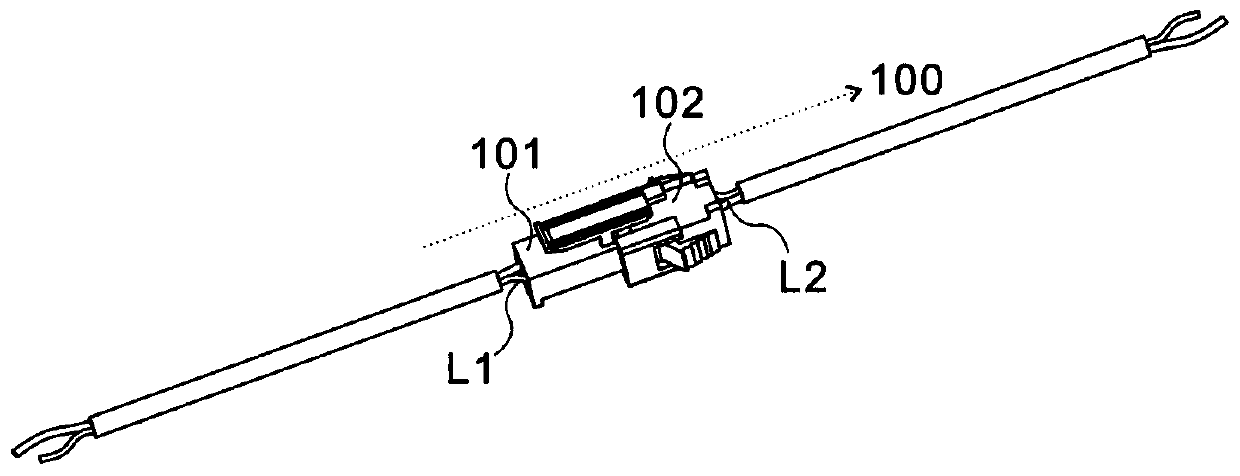
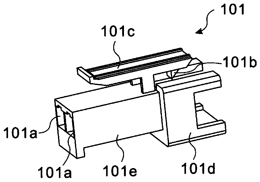
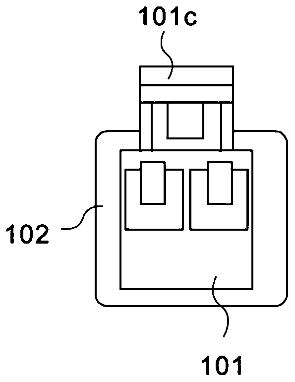
The invention discloses an electronic circuit connecting device. The electronic circuit connecting device comprises a first fitting assembly. The first fitting assembly comprises an occlusion member and a clamping member, wherein the occlusion member comprises a first through hole and an occlusion protruding block, the clamping member comprises a second through hole and a clamping protruding block, the first through hole communicates with the second through hole, and the occlusion protruding block is matched with the clamping protruding block. A first electric wire penetrates through the firstthrough hole and is connected with the occlusion member, a second electric wire penetrates through the second through hole and is connected with the clamping member, and the occlusion member is connected with the clamping member, so that the first electric wire and the second electric wire are connected. According to the electronic circuit connecting device, the sealing performance of the connection position is realized when the wires are connected, the contact of the connection between the two wires are more thorough in the extrusion process, the situation of poor contact is avoided, and after the electronic circuit connecting device is used in large machinery, wires on the machinery are convenient to carry and disassemble.

Description

technical field [0001] The invention relates to the field of electronic technology, in particular to an electronic circuit connection device. Background technique [0002] At present, when dealing with the connection between two or more individual wires, the following methods are usually used: first, the insulation protection layer of the wires is stripped, the wire cores are exposed and connected, and an insulating tape is used to wrap the connected cores . However, in the above method using the insulating tape, a tool for peeling off the insulating protective layer and winding the wire core is required. Also, the connection operation is complicated and troublesome. [0003] Second, peel off the insulation protection layer of the wire, and then clamp the wire core on the conductor in the connector, usually by screws. However, such a connection method also needs to use a tool for stripping the insulating layer, and its operation is also troublesome and complicated. If the...

Claims


Application Information

Patent Timeline
Patent Type & Authority Patents(China)
IPC IPC(8): H01R31/06H01R13/52H01R13/639
CPCH01R13/52H01R13/639H01R31/06
Inventor 严大虎王均霞陈思涛
Owner JIANGNAN UNIV
Learn More