Support image display device, support image display method, and support image display program
A technology for auxiliary images and display devices, which is applied in the directions of maps/plans/charts, image data processing, image data processing, etc., and can solve problems such as driver confusion.
- Summary
- Abstract
- Description
- Claims
- Application Information
AI Technical Summary
Problems solved by technology
Method used
Image

Examples
Embodiment approach 1
[0035] ***Description of structure***
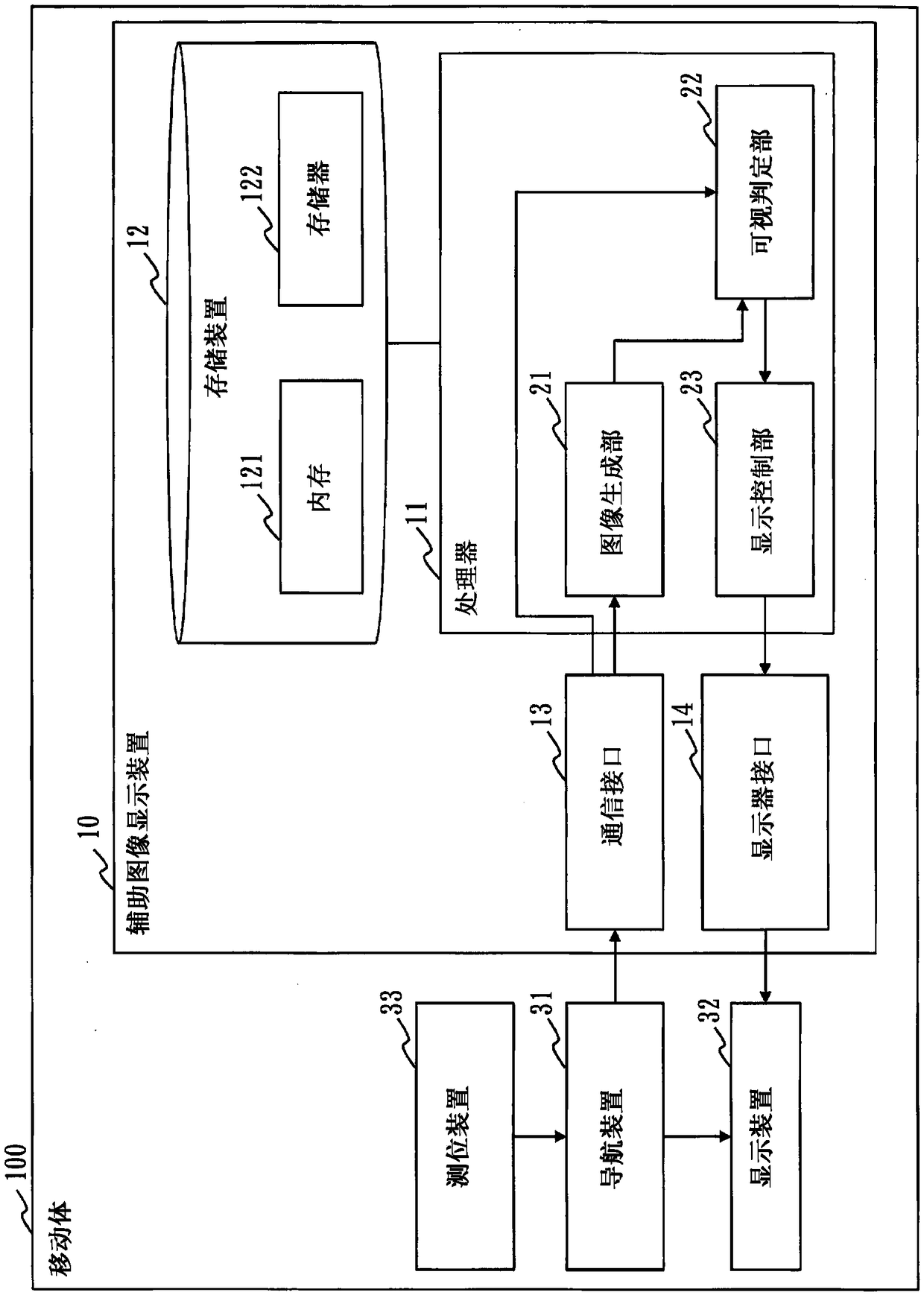
[0036] refer to figure 1 The configuration of the auxiliary image display device 10 according to Embodiment 1 will be described.
[0037] The auxiliary image display device 10 is a computer mounted on the mobile body 100 , and performs display control of POI (Point Of Interest) information to be displayed on the display device 32 by the navigation device 31 . In Embodiment 1, the mobile body 100 is a vehicle. The mobile body 100 is not limited to a vehicle, and may be other types such as ships and pedestrians.
[0038] The auxiliary image display device 10 has a processor 11 , a storage device 12 , a communication interface 13 , and a display interface 14 . The processor 11 is connected to other hardware via signal lines, and controls these other hardware.
[0039] The processor 11 is an IC (Integrated Circuit) that performs processing. As a specific example, the processor 11 is a CPU (Central Processing Unit), a DSP (Digital Signal...
Deformed example 1
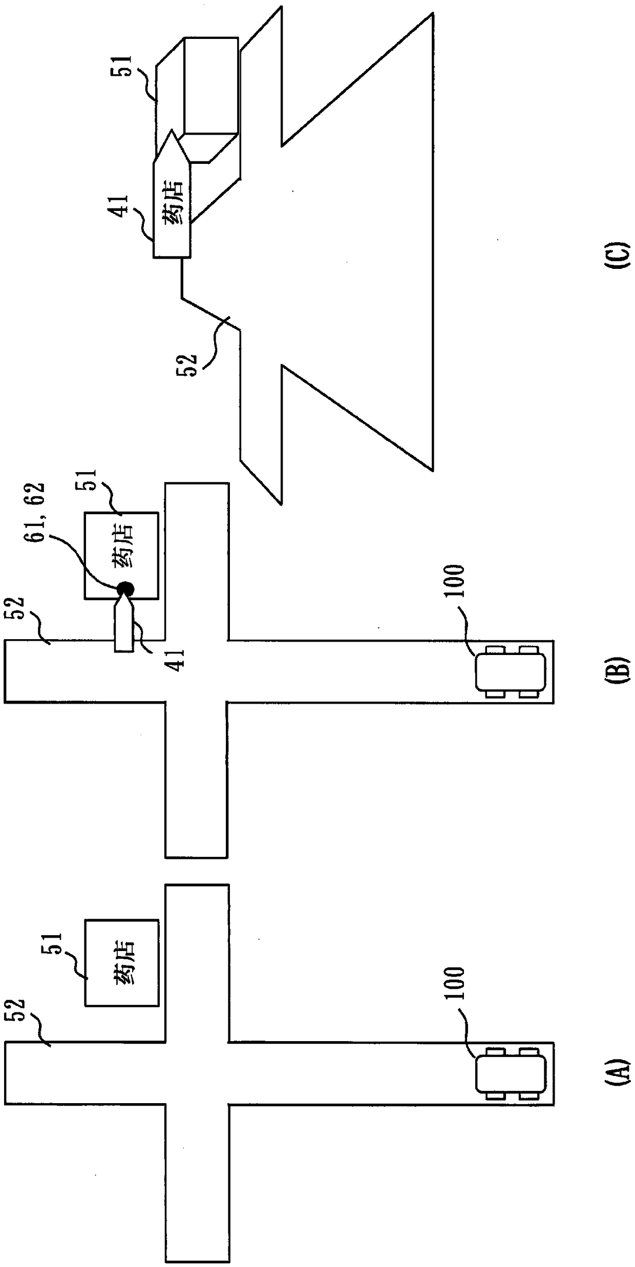
[0097] In Embodiment 1, the reference position 61 is a point on the object 51 . However, as Modification 1, the reference position 61 may be a point in the vicinity of the object 51 at a position offset from the object 51 . As a specific example, the reference position 61 may be a point closer to the road 52 than the object 51 .
[0098] Regarding Modification 1, differences from Embodiment 1 will be described.
[0099] In Modification 1, the method of specifying the reference position 61 in step S12 is different.
[0100] The image generator 21 specifies the point at which the object 51 is closest to the road 52 among the four points based on the latitude and longitude of the four points represented by the POI information, and calculates a point from the specified point to a point diagonal to the object 51. The position offset by a certain distance. The image generating unit 21 sets a position shifted from the calculated point to the road 52 to the outside of the object 51...
Deformed example 2
[0109] In Embodiment 1, when the reference range 62 cannot be visually recognized, the auxiliary image 41 is moved toward the road 52 . However, as Modification 2, when the reference range 62 cannot be visually recognized, and when a part of the object 51 can be visually recognized from the driver, the position indicated by the auxiliary image 41 may be set to be the center of the object 51. The auxiliary image 41 is moved so as to be visible from the driver and displayed. That is, when the structure 53 does not overlap part of the object 51 in the scenery, the auxiliary image 51 may be set so that the position indicated by the auxiliary image 41 is a position in the object 51 that does not overlap the structure 53 . Display after moving.
[0110] refer to Figure 14 The visibility judgment process in step S2 of Modification 2 will be described.
[0111] The processing of step S21~step S26 and Figure 6 The processing of steps S21 to S26 is the same.
[0112] In step S27 ...
PUM
 Abstract
Description
Claims
Application Information
 - R&D Engineer
- R&D Manager
- IP Professional
- Industry Leading Data Capabilities
- Powerful AI technology
- Patent DNA Extraction
Browse by: Latest US Patents, China's latest patents, Technical Efficacy Thesaurus, Application Domain, Technology Topic.
© 2024 PatSnap. All rights reserved.Legal|Privacy policy|Modern Slavery Act Transparency Statement|Sitemap