Supercharge Your Innovation With Domain-Expert AI Agents!

Switching device for conducting and interrupting electrical currents

A technology for switching equipment and cutting off current, which is applied in the field of switching equipment and can solve problems such as undesired switching arcs

Active Publication Date: 2018-11-23
EATON INTELLIGENT POWER LIMITED
View PDF7 Cites 2 Cited by
  • Summary
  • Abstract
  • Description
  • Claims
  • Application Information

AI Technical Summary

Problems solved by technology

Even in the case of hybrid switches with a mechanical switching device in the form of a vacuum switching chamber for conducting and breaking very high currents, as is known, for example, from German laid-open patent application DE 10 2013 114 260 A1, in some cases It can lead to the formation of undesired switching arcs

Method used


Image

  • Switching device for conducting and interrupting electrical currents
  • Switching device for conducting and interrupting electrical currents
  • Switching device for conducting and interrupting electrical currents

Examples


Embodiment Construction

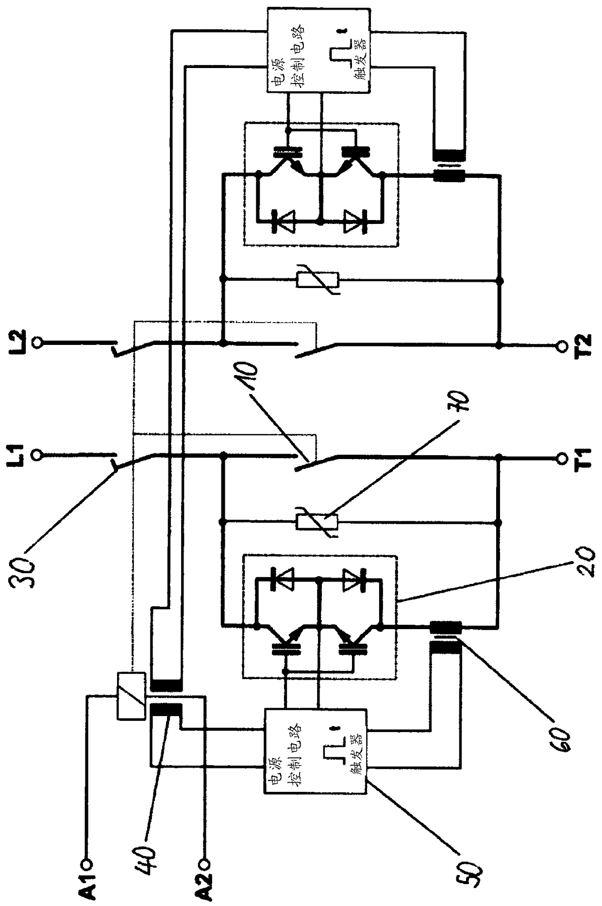
[0023] figure 1 A block diagram of a switching device according to the invention for a polarity-independent 2-pole switching device is shown. The connection terminals of the switching device for the two poles are designated L1, T1 and L2, T2, respectively. The switching device largely corresponds with respect to circuit technology to that described in German Published Patent Application DE 10 2013 114 259 A1 and described here in figure 1 device shown in. The device according to the invention described below differs from this known device by the switching electronics 50 , which are designed for a specific trigger control of the semiconductor switch 20 , as will be explained in more detail in the following description. The switching electronics 50 can be implemented, for example, by a processor and a memory, in particular a microcontroller, wherein a program is stored in the memory, which program components the processor to carry out the method steps leading to the The speci...


PUM


Abstract

The invention relates to a switching device for conducting and interrupting electric currents, comprising a first mechanical contact assembly (10), a semiconductor switch (20), which is connected in parallel with the first mechanical contact assembly, a second mechanical contact assembly (30), which is connected in series with the first mechanical contact assembly, an auxiliary coil (40), which isgalvanically isolated from the circuit of a switching drive for moving contacts of the first and second mechanical contact assemblies and is electromagnetically coupled to a coil of the switching drive in such a way that a voltage is produced in the auxiliary coil when the voltage supply of the switching drive is switched off, and switching electronics (50), which are designed to switch the semiconductor switch (20) on and off and which are supplied by the voltage produced in the auxiliary coil when the voltage supply of the switching drive is switched off. According to the invention, the switching electronics (50) are designed to switch the semiconductor switch (20) on and off multiple times according to a predefined sequence during an opening operation of the first and the second mechanical contact assembly (10, 30), in order to interrupt electrical currents.

Description

technical field [0001] The present invention relates to a switchgear for conducting and breaking current, in particular a hybrid switching assembly for conducting and breaking high DC current and low frequency AC current, and a switchgear having such a switchgear. Background technique [0002] German Published Patent Application DE 10 2013 114 259 A1 describes an advantageous variant of a hybrid switching assembly in which the time of the current load of the power semiconductors is minimized for the longest possible life expectancy and the smallest possible size, especially for the current range It is important for power contactors with hundreds of amperes. In order to minimize the duration of the load current flowing through the power semiconductors, the commutation instants are captured by the current converters and the current flow through the semiconductors is only maintained until a sufficient electrical strength has been achieved for the opened mechanical switching pat...

Claims


Application Information

Patent Timeline
IPC IPC(8): H01H9/54H01H33/04
CPCH01H9/542H01H33/04H01H2009/544H01H9/547H01H33/596H01H33/66H03K17/56
Inventor G·施米茨J·迈斯纳M·乌德尔霍芬M·沃朗O·克雷夫特
Owner EATON INTELLIGENT POWER LIMITED
Features
  • R&D
  • Intellectual Property
  • Life Sciences
  • Materials
  • Tech Scout
  • Unparalleled Data Quality
  • Higher Quality Content
  • 60% Fewer Hallucinations
Learn More