Cable pay-off device

A technology of pay-off device and branching device, which is applied in conductor/cable supply device, cable/conductor manufacturing, circuit, etc. It can solve the problems of lowering the quality of cables and contamination of wires with sundries, etc., so as to improve performance and service life Effect

Inactive Publication Date: 2018-11-27
德阳市德东电工机械制造有限公司
View PDF0 Cites 2 Cited by
  • Summary
  • Abstract
  • Description
  • Claims
  • Application Information

AI Technical Summary

Problems solved by technology

[0003] The invention provides a cable pay-off device to solve the problem that the wires are contaminated with impurities and reduce the quality of the cable produced

Method used


Image

  • Cable pay-off device
  • Cable pay-off device

Examples


Embodiment Construction

[0014] The present invention will be described in further detail below in conjunction with the accompanying drawings and specific embodiments. Embodiments of the present invention include, but are not limited to, the following examples.

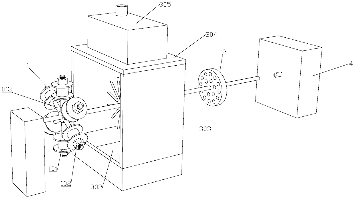
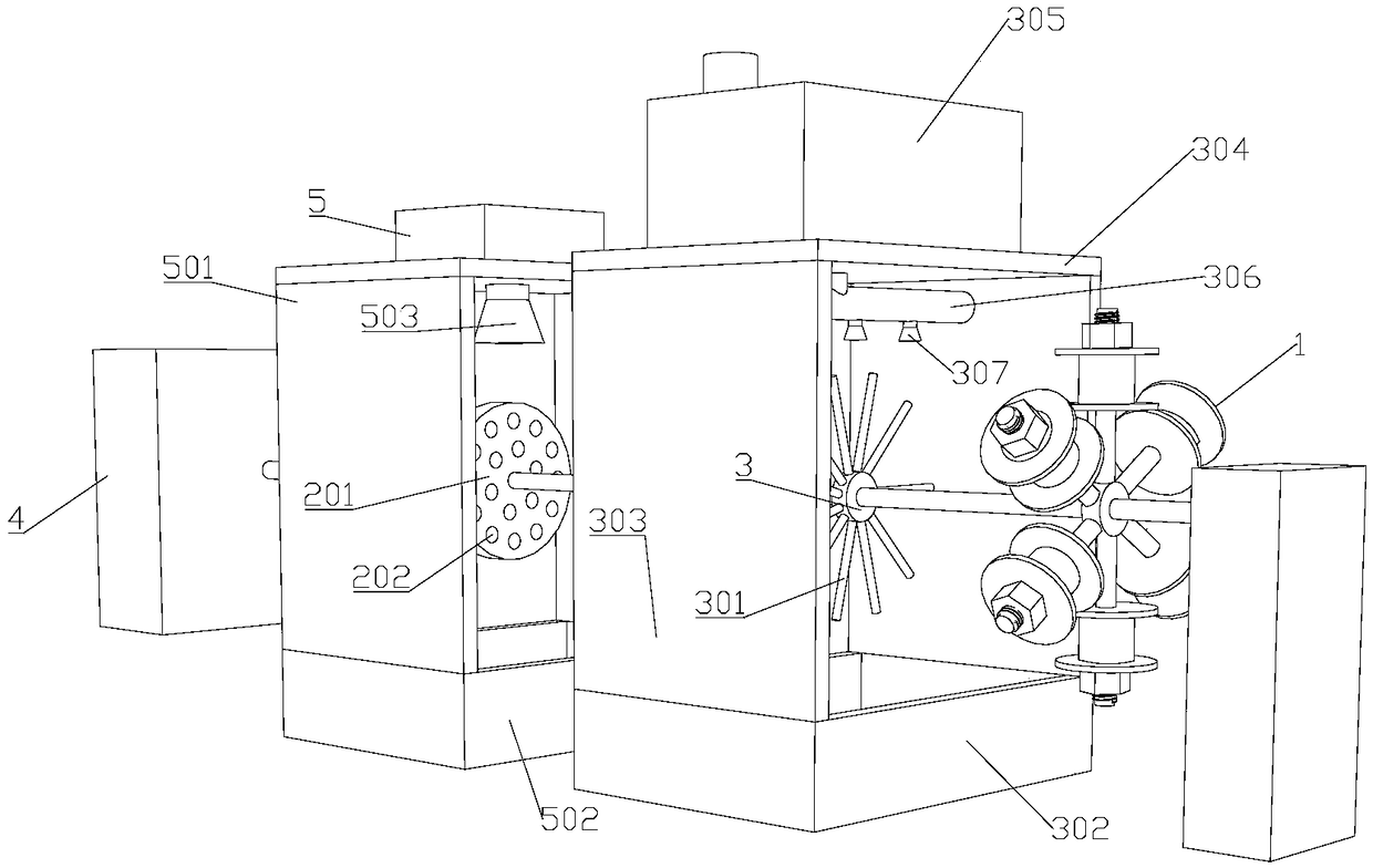
[0015] like figure 1 , figure 2 As shown, a cable pay-off device 1 is used to feed wires into a stranding machine 4, including a pay-off device 1, a wire splitting device 2, and a wire stranding machine 4 arranged in sequence along the wire incoming direction, wherein the pay-off device 1 One side is provided with a supporting platform, and the supporting platform is fixedly connected with a bearing shaft. The wire releasing device 1, the wire dividing device 2 and the wire twisting machine 4 are all fixed on the bearing shaft, and are supported by the bearing shaft; the wire releasing device 1 and the wire dividing device 2 is provided with a partition plate 3, and the partition plate 3 is evenly distributed along the circumferential dire...


PUM


Abstract

The invention discloses a cable pay-off device. The cable pay-off device is used for feeding wires into a twisting machine, and the cable pay-off device comprises a pay-off device, a separating deviceand the twisting machine which are arranged in a wire inlet direction in sequence, wherein a separating tray is arranged between the pay-off device and the separating device, a plurality of separation strips are evenly distributed in a circumferential direction of the separating tray, a first water receiving tray is arranged under the separating tray, first supporting boards are fixedly arrangedon the side walls of the first water receiving tray, a first installation board located over the separating tray is arranged on the tops of the first supporting boards, a water tank is fixedly arranged on the top of the first installation board, a water delivery pipe located over the separating tray is arranged under the first installation board, the two ends of the water delivery pipe are fixedlyconnected with the first supporting boards, the water delivery pipe is communicated with the water tank, and a plurality of spray heads with outer outlets facing the separating tray are arranged on the water delivery pipe. By means of the pay-off device, impurities on the wires can be cleaned away, and the use performance and the service life of a prepared cable are improved.

Description

technical field [0001] The invention relates to the technical field of cable preparation, in particular to a cable pay-off device. Background technique [0002] The cable is usually twisted by several or several groups of wires, each group of wires is insulated from each other, and is usually twisted around a center, and the entire outer surface is covered with a highly insulating coating. However, the existing twisting machine needs to put a plurality of winding reels with wires wound on it when twisting the wires, and lead out the wires on the winding reels, and then form a cable after being stranded by the twisting machine. If the spare parts are produced, they will inevitably be contaminated with more dust and other sundries during the storage process. If these sundries are twisted together with the wires in the cable, the performance and safety performance of the produced cables will be greatly reduced. Contents of the invention [0003] The invention provides a cabl...

Claims


Application Information

Patent Timeline
Patent Type & Authority Applications(China)
IPC IPC(8): H01B13/00H01B13/02B08B3/02
CPCH01B13/0003B08B3/022H01B13/0036H01B13/0207H01B13/0285
Inventor 张大海
Owner 德阳市德东电工机械制造有限公司
Why Eureka
Try Eureka