
Forming die assembling structure of die-casting machine

A technology for forming molds and assembling structures, applied in the field of die casting, can solve problems such as inconvenience, time-consuming and laborious, and achieve the effects of high efficiency, convenient and quick installation and separation

Inactive Publication Date: 2018-11-30
太仓鸿鑫精密压铸有限公司
View PDF3 Cites 0 Cited by
  • Summary
  • Abstract
  • Description
  • Claims
  • Application Information

AI Technical Summary

Problems solved by technology

[0003] When the existing manipulator installs or separates the gripper, it is time-consuming and laborious, which is very inconvenient

Method used


Image

  • Forming die assembling structure of die-casting machine
  • Forming die assembling structure of die-casting machine

Examples


Embodiment Construction

[0011] The specific implementation manners of the present invention will be further described below in conjunction with the drawings and examples. The following examples are only used to illustrate the technical solution of the present invention more clearly, but not to limit the protection scope of the present invention.

[0012] The technical scheme of concrete implementation of the present invention is:

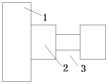
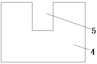
[0013] Such as figure 1 and figure 2 as shown,

[0014] An assembly structure of a molding die 1 of a die-casting machine, including a body and a mold 1. The body is supported by a mounting plate 4 through a bracket. The mounting plate 4 extends downward from the upper edge with a hanging groove 5. The back of the template is provided with a mounting column 2. The side wall of the mounting column 2 is provided with a limiting groove 3, the mounting column 2 is placed in the hanging groove 5, and the junction of the mounting plate 4 and the hanging groove 5 is clamped i...


PUM


Abstract

The invention discloses a forming die assembling structure of a die-casting machine. The forming die assembling structure of the die-casting machine comprises a body and a die, wherein the body supports a mounting plate through a support; a hanging groove extends downwards from the upper edge of the mounting plate; a mounting column is arranged on the back of a template; a limiting groove is formed in a side wall of the mounting column; the mounting column is placed in the hanging groove; and the position where the mounting plate is connected with the hanging groove is clamped in the limitinggroove. The forming die assembling structure of the die-casting machine has the beneficial effects that the assembling structure is speedy and convenient to mount and separate and is high in efficiency.

Description

technical field [0001] The invention relates to the technical field of die casting, in particular to a molding die assembly structure of a die casting machine. Background technique [0002] With the development and progress of society, more and more industrial robots appear and show their talents. Robots are mainly composed of human-like arms to replace human beings in routine work by grabbing items and operating them by hand. At present, there are many forms of clamping structures for robots to grab objects, such as clamping type, holding type, and adsorption type. According to the driving mode, it can be divided into hydraulic type, pneumatic type, electric type and so on. Among them, the pneumatic clamping clamping structure is the most commonly used. [0003] When the existing manipulator installs or separates the gripper, it is time-consuming and labor-intensive, which is very inconvenient. Contents of the invention [0004] The purpose of the present invention is...

Claims


Application Information

Patent Timeline
Patent Type & Authority Applications(China)
IPC IPC(8): B22D17/22
CPCB22D17/22
Inventor 钱伟国
Owner 太仓鸿鑫精密压铸有限公司
Learn More