Fire-fighting escape channel for outer side of building

An escape route and fire-fighting technology, which is applied in construction, building rescue, building construction, etc., can solve the problems of poor anti-theft performance and low safety, and achieve the effects of improving safety, convenient use, and improving safety and anti-theft performance

Inactive Publication Date: 2018-11-30
马琪吉
View PDF0 Cites 2 Cited by
  • Summary
  • Abstract
  • Description
  • Claims
  • Application Information

AI Technical Summary

Problems solved by technology

[0003] However, the fire-fighting escape channel used on the outside of the existing building has a simple structure, and an escape ladder is simply installed on the outside of the wall for escape. Poor, secondly simply set up an escape ladder to climb and escape, the safety in the escape process is low, so it cannot meet the needs of users

Method used


Image

  • Fire-fighting escape channel for outer side of building
  • Fire-fighting escape channel for outer side of building
  • Fire-fighting escape channel for outer side of building

Examples


Embodiment 1

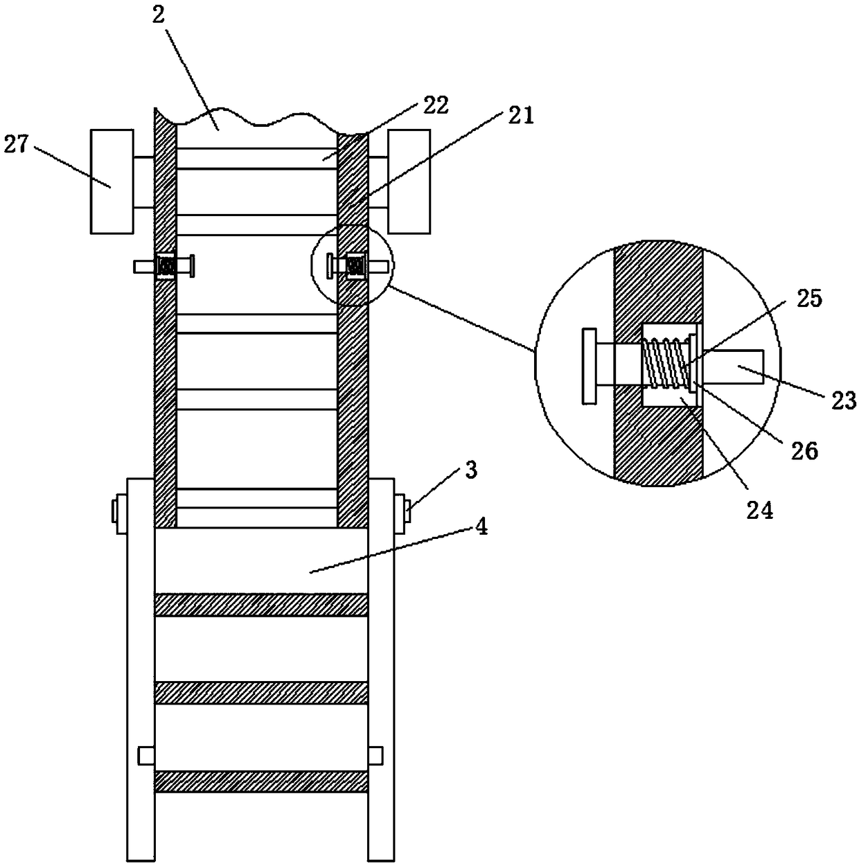
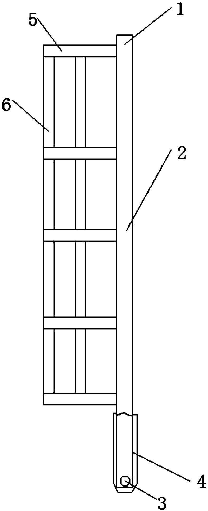
[0025] Example 1: refer to Figure 1-4 , a fire escape passage for the outside of a building, including an escape passage body 1, the escape passage body 1 is composed of a first escape ladder 2 and a second escape ladder 4, and the second escape ladder 4 is connected to the first escape ladder through the rotating shaft 3. At the bottom end of 1, the first escape ladder 2 is composed of two first vertical beams 21 that are parallel to each other, and a plurality of cross bars 22 for stepping and climbing are welded at equal distances between the two first vertical beams 21. The vertical beam 21 is provided with a limit rod 23 that is perpendicular to the first vertical beam 21. A groove 24 is formed inside the first vertical beam 21, and a limit spring 25 is sleeved on the limit rod 23 inside the groove 24. , the limit rod 23 is welded with a limit ring 26 for use with the limit spring 25, the outer wall of the first vertical beam 21 is welded with a fixed block 27, and the s...

Embodiment 2

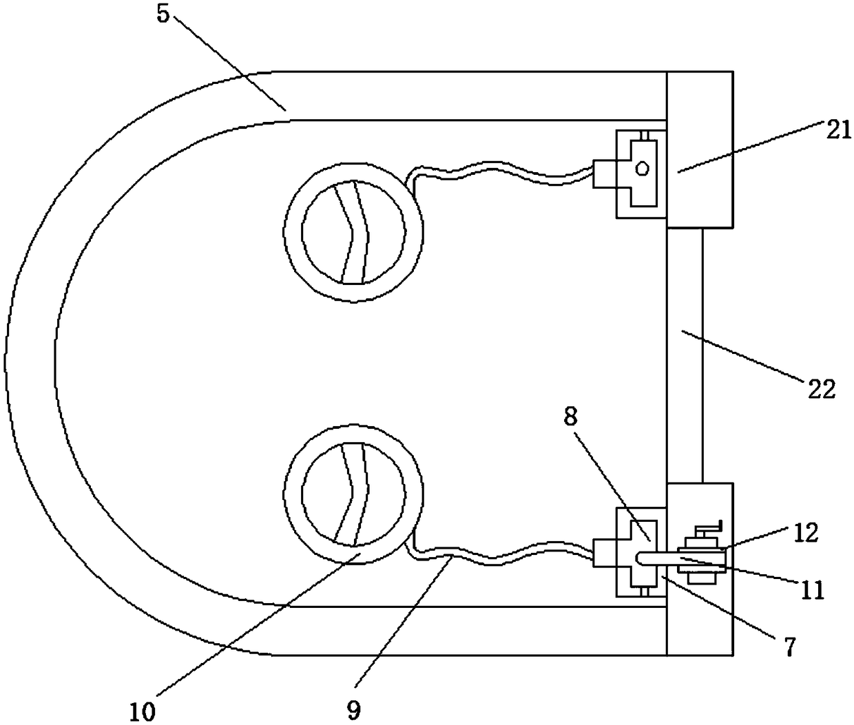
[0026] Embodiment 2: refer to Figure 2-3 , a plurality of annular frames 5 are welded equidistantly along the vertical direction on the outer wall of the first escape ladder 2, and connecting rods 6 are welded between the plurality of annular frames 5. There are three connecting rods 6 in total, and the three connecting rods are 6 is distributed in an arc shape, and the distance between two adjacent connecting rods 6 is equal. The ring frame 5 can limit the user climbing on the first escape ladder and improve the safety of their climbing. The connecting rod 6 is used for It is used for auxiliary fixing of the plurality of ring frames 5 to improve its strength.

Embodiment 3

[0027] Embodiment 3: refer to figure 1 and Figure 4 , the second vertical beam 41 is provided with an engaging hole 43 for use with the limit rod 26, and a snap ring 46 is fixed on the outer wall of the second vertical beam 41 through the fixing rod 45, and the snap ring 46 can be matched with the preset on the building wall. The limit block is used to improve the stability of the second escape ladder 4. A cross beam 44 is welded between the top ends of the two second vertical beams 41, and the cross beam 44 is used to relatively fix the two second vertical beams 41.


PUM


Abstract

The invention discloses a fire-fighting escape channel for the outer side of a building. The fire-fighting escape channel comprises an escape channel body. The escape channel is composed of a first escape ladder and a second escape ladder, and the second escape ladder is rotationally connected to the bottom end of the first escape ladder through a rotating shaft. The first escape ladder is composed of two first vertical beams which are mutually parallel, and a plurality of transverse rods used for treading and climbing are welded between the two first vertical beams at equal distances. According to the fire-fighting escape channel, the escape channel is composed of the first escape ladder and the second escape ladder, and the second escape ladder is rotationally connected to the bottom endof the first escape ladder through the rotating shaft; and in the process that the fire-fighting escape channel is not used, the second escape ladder can be rotated onto the first escape ladder through the rotating shaft and is fixed in the mode that limiting columns are clamped into clamping holes, thus after mounting, other people cannot climb into the building through the second escape ladder,wherein the building is provided with the escape channel, and the safety anti-theft property of the building is improved.

Description

technical field [0001] The invention relates to the technical field of building facilities, in particular to a fire escape channel for the outside of a building. Background technique [0002] Anti-channel refers to the channel for firefighters to rescue and evacuate trapped people, such as stair entrances and aisles, where fire indicators are installed. Fire channels play a role that cannot be underestimated in various dangerous situations. [0003] However, the existing fire escape channel on the outside of the building has a simple structure. It is simple to set an escape ladder on the outside of the wall for escape. After installation, during the use process, the bad guys are easy to climb from the escape ladder to the interior of the building, resulting in a relatively low anti-theft performance. Second, simply setting up an escape ladder for climbing and escaping has low safety in the escape process, so it cannot meet the needs of users. SUMMARY OF THE INVENTION [0...

Claims


Application Information

Patent Timeline
Patent Type & Authority Applications(China)
IPC IPC(8): E06C9/08E06C7/18A62B1/00
CPCE06C9/08A62B1/00E06C7/185E06C7/186
Inventor 马琪吉
Owner 马琪吉
Why Eureka
Try Eureka