A kind of automatic window opening and closing method and automatic window closing structure

An automatic, window-closing technology, applied in power control mechanisms, door/window accessories, building structures, etc., can solve problems such as potential safety hazards, and achieve the effect of high degree of automation, easy remote operation, and convenient window opening operation.

Active Publication Date: 2018-04-27
陈星宇
View PDF10 Cites 0 Cited by
  • Summary
  • Abstract
  • Description
  • Claims
  • Application Information

AI Technical Summary

Problems solved by technology

[0006] Although the above-mentioned structure can realize the electric opening and closing of the window, but considering the safety, if the window cannot be locked when the window is closed, it is easy to cause certain safety hazards

Method used


Image

  • A kind of automatic window opening and closing method and automatic window closing structure
  • A kind of automatic window opening and closing method and automatic window closing structure
  • A kind of automatic window opening and closing method and automatic window closing structure

Examples


Embodiment 1

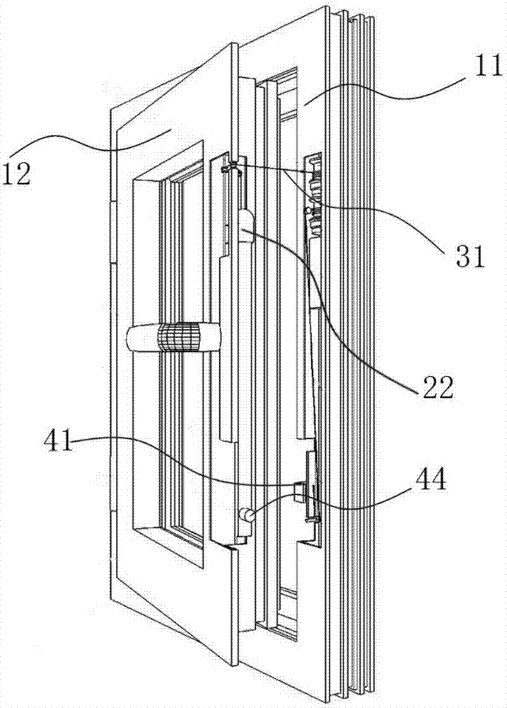
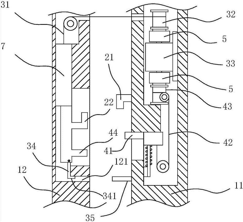
[0040] see Figure 1 to Figure 4 , the automatic window closing structure of the present embodiment comprises a window frame 11, a sash 12, a window lock assembly, a window closing device and a window opening device, and the sash 12 adopts a casement window installation structure (that is, the sash 12 is hinged on the window frame 11), and the window lock The assembly includes a lock seat 21 and a lock block 22 for snapping into the lock seat 21. The lock seat 21 is fixed on the window frame 11, and the lock block 22 is slidably installed on the window sash 12. The window closing device includes a traction rope 31, a traction cylinder 32. The drive motor 33 has a limit structure, one end of the traction rope 31 is connected to the lock block 22, and the other end of the traction rope 31 is wound on the traction cylinder 32, the limit structure includes a limit rod 34 and an unlocking member 35, The unlocking member 35 is fixed on the window frame 11, one end of the limiting ro...

Embodiment 2

[0050] see Figure 5 , the structure of the automatic window closing structure in this embodiment is basically the same as that in Embodiment 1, the difference is that the tightening mechanism 7 adopts a pulley block mechanism, and the pulley block mechanism includes a static pulley block 61, a movable pulley block 62, and a static pulley frame 63 , movable pulley frame 64, counterweight 65, static pulley block 61 is rotatably installed on the static pulley block 63, and movable pulley block 62 is rotatably installed on the movable pulley frame 64, and the other end of described traction rope 31 is wound around movable pulley block 62, static pulley block 61 After being fixed on the movable pulley frame 64, the counterweight 65 is connected on the movable pulley frame 64.

Embodiment 3

[0052] see Figure 6 , the structure of the automatic window closing structure in this embodiment is basically the same as that in Embodiment 1, the difference is that the lock block 22 is rotatably mounted on the window sash 12, the traction rope 31 is connected to the lock block 22, and the lock block 22 is pulled by the traction rope 31 , through the principle of leverage, the lock block 22 rotates and snaps into the lock seat 21 .


PUM


Abstract

The invention discloses an automatic window opening and closing method and an automatic window closing structure. The automatic window opening and closing method comprises the following window closing steps: a lock block is limited to a non-window-locking position by a limiting structure, and the lock block on a sash is pulled in the forward direction through a pulling rope to enable the sash to move to a closed state relative to a window frame; and when the sash is in the closed state, the window frame acts on the limiting structure to enable the limiting structure to automatically relieve limitation on the lock block, then the lock block can be continually pulled by the pulling rope to move to a window-locking position, and at the moment, the lock block is clamped in a lock seat to finish window closing. The automatic window opening and closing method can realize the window locking function during window closing, is particularly suitable for realizing window closing and locking and unlocking for window opening when a user is not on site, and is high in degree of automation, simple in control method and easy for remote operation.

Description

technical field [0001] The invention relates to an automatic window opening and closing method and an automatic window closing structure. Background technique [0002] In order to avoid damage to indoor items when it is windy or rainy, various window closing devices with automatic window closing functions have appeared on the market, and there are many related documents, such as: [0003] The invention of application number: 201610022695.2 discloses an automatic window closer, including a housing, a power supply, a temperature and humidity sensor, a photosensitive sensor, a reel rope, a microcontroller installed in the housing, and a first Relay, the first motor, the first reel and the reel rope, the power supply, the temperature and humidity sensor and the photosensitive sensor are electrically connected to the microcontroller, one end of the reel rope is wound on the first reel, and the other end is installed on the on the windows. [0004] The invention of application n...

Claims


Application Information

Patent Timeline
Patent Type & Authority Patents(China)
IPC IPC(8): E05F15/643E05B53/00
CPCE05B53/005E05F15/643
Inventor 陈星宇
Owner 陈星宇
Why Eureka
Try Eureka