[0021] The following will clearly and completely describe the technical solutions in the embodiments of the present invention with reference to the accompanying drawings in the embodiments of the present invention. Obviously, the described embodiments are only some, not all, embodiments of the present invention. Based on the embodiments of the present invention, all other embodiments obtained by persons of ordinary skill in the art without making creative efforts belong to the protection scope of the present invention.
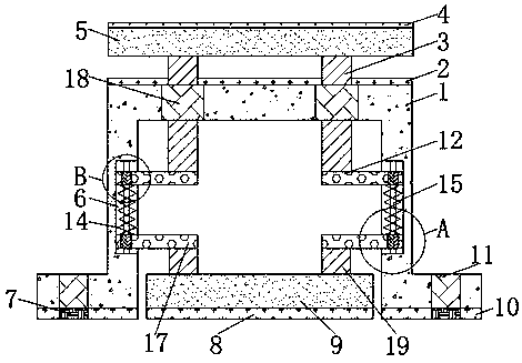
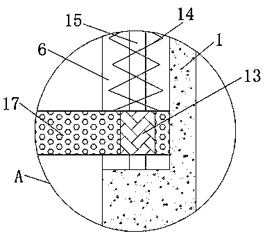
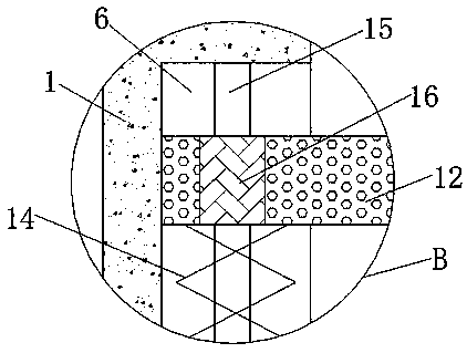
[0022] see Figure 1-3 , the present invention provides a technical solution: an anti-seismic stamping bracket assembly, including a bracket body 1, two symmetrical first through holes 11 are opened on the bottom surface of the bracket body 1, and two symmetrical first through holes 11 are fixedly connected to the bottom surface of the bracket body 1. A symmetrical fourth shock absorbing pad 10, the fourth shock absorbing pad 10 performs shock absorption to the bracket body 1 for the first time, increasing the shock absorbing effect of the stamping bracket, and the bottom surface of each fourth shock absorbing pad 10 is provided with a fourth The through holes 7, and the two fourth through holes 7 communicate with the two first through holes 11 respectively, so that the stamping bracket is more convenient to install, and the first shock absorbing plate 5 is placed on the top of the bracket body 1, and the first shock absorbing plate 5 The upper surface of the plate 5 is fixedly connected with the first shock absorbing pad 4, which can perform the first shock absorption on the first shock absorbing plate 5 and increase the shock absorbing effect of the stamping bracket. The upper surface of the bracket body 1 is fixedly connected with the third shock absorbing pad 4. Pad 2, and the third damping pad 2 is located below the first damping plate 5, which can perform secondary shock absorption on the first damping plate 5, further increasing the damping effect of the stamping bracket, the first damping plate 5 Two symmetrical support rods 3 are fixedly connected to the bottom surface of the support body 1, and two symmetrical second through holes 18 are opened on the upper surface of the bracket body 1, and the two second through holes 18 correspond to the two support rods 3, The bottom end of each support rod 3 passes through the second through hole 18 and extends to the inside of the groove of the bracket body 1. Two symmetrical support plates 12 are placed in the groove of the bracket body 1. The support rod 3 and the support plate 12, the force received by the first damping plate 5 can be transmitted to the damping spring 14, and the force can be reduced by the damping spring 14, which solves the problem that the stamping bracket does not have shock-absorbing performance or the shock-absorbing performance is not good. Good question, the inner wall of the groove of the bracket body 1 is provided with two symmetrical chute 6, and the inside of each chute 6 is fixedly connected with a sliding rod 15, and the upper surfaces of the two support plates 12 are far away from each other. There is a fifth through hole 16, and the two sliding rods 15 are respectively socketed with the two fifth through holes 16, which can make the first shock absorbing plate 5 more stable when rising or falling, and avoid the first shock absorbing plate 5 There is a phenomenon of inclination or jamming when rising or falling. The ends of the two support plates 12 that are far away from each other are snapped into the inside of the chute 6, and the inside of the groove of the bracket body 1 is placed with the second damping plate 9, and the first The second damping plate 9 is located below the support plate 12, and the bottom surface of the second damping plate 9 is fixedly connected with a second shock absorbing pad 8, which can first damp the second damping plate 9 and increase the shock absorption of the stamping support. As a result, the upper surface of the second damping plate 9 is fixedly connected with two symmetrical support columns 19, and the upper surface of each support column 19 is fixedly connected with a support block 17, and the two support plates 12 are respectively located on the two support columns. Above the block 17, the supporting column 19 and the supporting block 17 are used together to transmit the force received by the second damping plate 9 to the damping spring 14, and the force is reduced by the damping spring 14, which further solves the problem of stamping. The bracket does not have shock-absorbing performance or the shock-absorbing performance is not good. The upper surface of each support block 17 away from one end is provided with a third through hole 13, and the two slide bars 15 are connected with the two third through holes 13 respectively. Phase socket, can make the second damping plate 9 more when rising or falling It is more stable, avoiding the phenomenon that the second damping plate 9 is tilted or stuck when it rises or falls. The ends of the two support blocks 17 that are far away from each other are snapped into the inside of the chute 6, and the upper end of each support block 17 The surface is all fixedly connected with shock absorbing spring 14, and the bottom surface of each support plate 12 is all fixedly connected with the top of shock absorbing spring 14, and two slide bars 15 are socketed with two shock absorbing springs 14 respectively, prevents shock absorbing spring 14 There is a phenomenon of tilting or jamming when it is compressed by force.
[0023] Working principle: After the stamping bracket is installed, when the top is squeezed, the first shock absorbing plate 5 and the second shock absorbing plate 9 are squeezed, and the extrusion force of the first shock absorbing plate 5 passes through the support rod 3 And the support rod 3 is transmitted to the shock absorbing spring 14, the shock absorbing spring 14 is stressed and compressed, and this force is reduced, the second shock absorbing plate 9 is subjected to extrusion force, and the extrusion force of the second shock absorbing plate 9 passes through the support column 19 and the supporting block 17 are transmitted to the damping spring 14, and the damping spring 14 is compressed by force, and this force is reduced, and the first damping pad 4 and the second damping plate 9 on the upper surface of the first damping plate 5 The second shock pad 8 on the bottom surface and the fourth shock pad 10 on the bottom surface of the support 1 are compressed by this force, and the force is reduced. Through the above-mentioned multiple shock absorption, the support can be effectively protected, so that the stamped support does not It will be damaged due to external force, prolonging the life of the stamping bracket.
[0024] In summary, the anti-seismic stamping support assembly is provided with the first shock absorbing pad 4 on the upper surface of the first shock absorbing plate 5, the second shock absorbing pad 8 on the bottom surface of the second shock absorbing plate 9, and the bottom surface of the bracket 1. The combined use of the fourth shock absorbing pad 10 can slow down the external force received by the stamping bracket, and reduce the external force, so that the stamping bracket can perform shock absorption for the first time. By being provided with the third shock absorbing pad 2, it can When the shock absorbing plate 5 is under force and unloads downward, the second force unloading is performed on the first shock absorbing plate 5, which can better reduce the received external force. The force received by the first damping plate 5 can be transmitted to the damping spring 14, and the force can be reduced by the damping spring 14, which solves the problem that the stamping bracket does not have shock-absorbing performance or the shock-absorbing performance is not good. The cooperative use of the support column 19 and the support block 17 can make the force received by the second damping plate 9 be transmitted to the damping spring 14, and the force can be reduced by the damping spring 14, which further solves the problem that the stamping bracket does not have For the problem of poor shock absorption performance or shock absorption performance, through the cooperative use of the chute 6 and the slide bar 15, the first shock absorber 5 and the second shock absorber 9 can be raised or lowered by external force. Stuck or tilted.
[0025] It should be noted that in this article, relational terms such as first and second are only used to distinguish one entity or operation from another entity or operation, and do not necessarily require or imply that there is a relationship between these entities or operations. There is no such actual relationship or order between them.
[0026]Although the embodiments of the present invention have been shown and described, those skilled in the art can understand that various changes, modifications and substitutions can be made to these embodiments without departing from the principle and spirit of the present invention. and modifications, the scope of the invention is defined by the appended claims and their equivalents.