Power switch control equipment

A technology for controlling equipment and power switches, applied in the direction of electric switches, circuits, electrical components, etc., can solve the problems of inconvenient switch control, etc., and achieve the effect of convenient control and easy use

Active Publication Date: 2018-11-30
安徽信康电子科技有限公司
View PDF5 Cites 0 Cited by
  • Summary
  • Abstract
  • Description
  • Claims
  • Application Information

AI Technical Summary

Problems solved by technology

[0003] In order to overcome the disadvantage of inconvenient switch control in the ab

Method used


Image

  • Power switch control equipment
  • Power switch control equipment

Examples


Embodiment Construction

[0015] In order to enable those skilled in the art to better understand the technical solutions of the present invention, the present invention will be described more clearly and completely below in conjunction with the accompanying drawings in the embodiments. Of course, the described embodiments are only a part of the present invention. Not all, based on this embodiment, other embodiments obtained by those skilled in the art without creative efforts are all within the protection scope of the present invention.

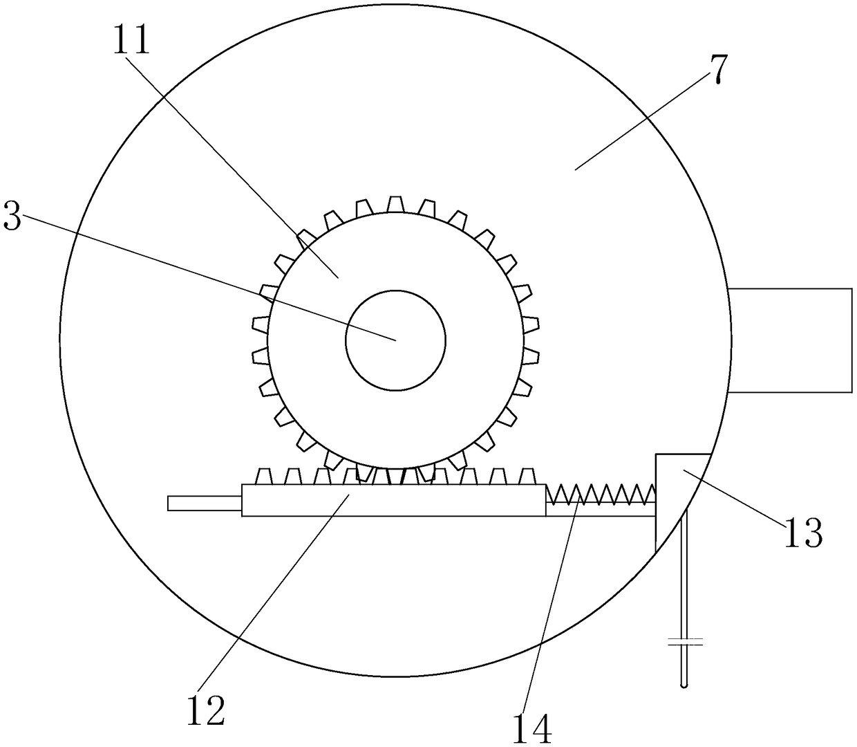
[0016] Such as Figure 1 to Figure 2 As shown, a power switch control device includes a circular main box 1, a transverse guide tube 2 is provided in the left middle part of the main box 1, a through groove 1a is opened in the left lower part of the main box 1, and the center of the main box 1 passes through The bearing is equipped with a round rod 3, and the front side of the round rod 3 is respectively equipped with a large round cake 4 and a small round cake 5 thr...


PUM

PropertyMeasurementUnit
Central angleaaaaaaaaaa

Abstract

The invention relates to power switch control equipment. The power switch control equipment comprises a circular main body box, wherein the middle part of the left side of the main body box is provided with a transverse guide pipe; a through groove is formed in the lower part of the left side of the main body box; a round rod is mounted in the center of the main body box through a bearing; a big round cake and a small round cake are correspondingly mounted in front of the round rod through key joint and bearing joint modes respectively; two ratchets are arranged on the arc surface of the smallround cake, a lug is arranged at an eccentric position on the front end face of the small round cake, a main driving block is mounted on the transverse guide pipe in a horizontal slip manner, the right end of the main driving block is welded with a linkage plate, and a matching groove for mounting the lug in a vertical slip manner is formed in the linkage plate. The power switch control equipmentis convenient to use, through the cooperation of pawls and the ratchets and the limitation of oscillating rods on the ratchets, the turning-on and turning-off of a control circuit can be realized bypulling a digging rope downwards in a single direction, and the relative control is convenient.

Description

technical field [0001] The invention relates to a switch device, in particular to a power switch control device. Background technique [0002] As we all know, the operation of large-scale machinery and equipment is inseparable from the supply and support of electricity. Therefore, there are extremely complex circuit systems and switchgear for controlling circuit on and off inside the machinery, but the problem is that when the traditional switchgear is used, The switch modes are all controlled by different operation modes, resulting in extremely inconvenient operation. Contents of the invention [0003] Now in order to overcome the defect of inconvenient switch control existing in the above technology, the present invention proposes a power switch control device. [0004] The technical problem to be solved by the present invention adopts the following technical solutions to realize: [0005] A power switch control device, comprising a circular main body box, a transverse...

Claims


Application Information

Patent Timeline
IPC IPC(8): H01H17/18
Inventor 叶泽民许玲萍方建兵
Owner 安徽信康电子科技有限公司
Why Eureka
Try Eureka