Clutch device

A clutch device and clutch technology, applied in clutches, friction clutches, fluid-driven clutches, etc., can solve problems such as time-consuming, large rotating mass, etc., and achieve the effects of avoiding waste, small installation space, and compact structure

Active Publication Date: 2018-12-04
SCHAEFFLER TECH AG & CO KG
View PDF20 Cites 1 Cited by
  • Summary
  • Abstract
  • Description
  • Claims
  • Application Information

AI Technical Summary

Problems solved by technology

[0005] Considering the many components connected on the drive side, the construction of such a clutch arrangement is complex, in particular a large rotating mass is generated on the drive side

Method used


Image

  • Clutch device
  • Clutch device

Examples


Embodiment Construction

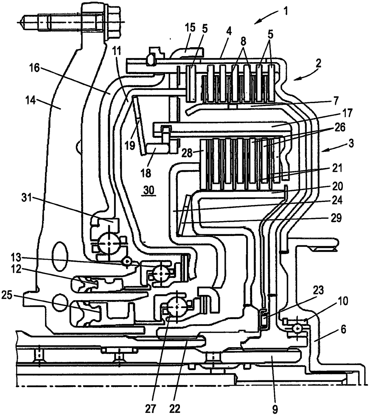
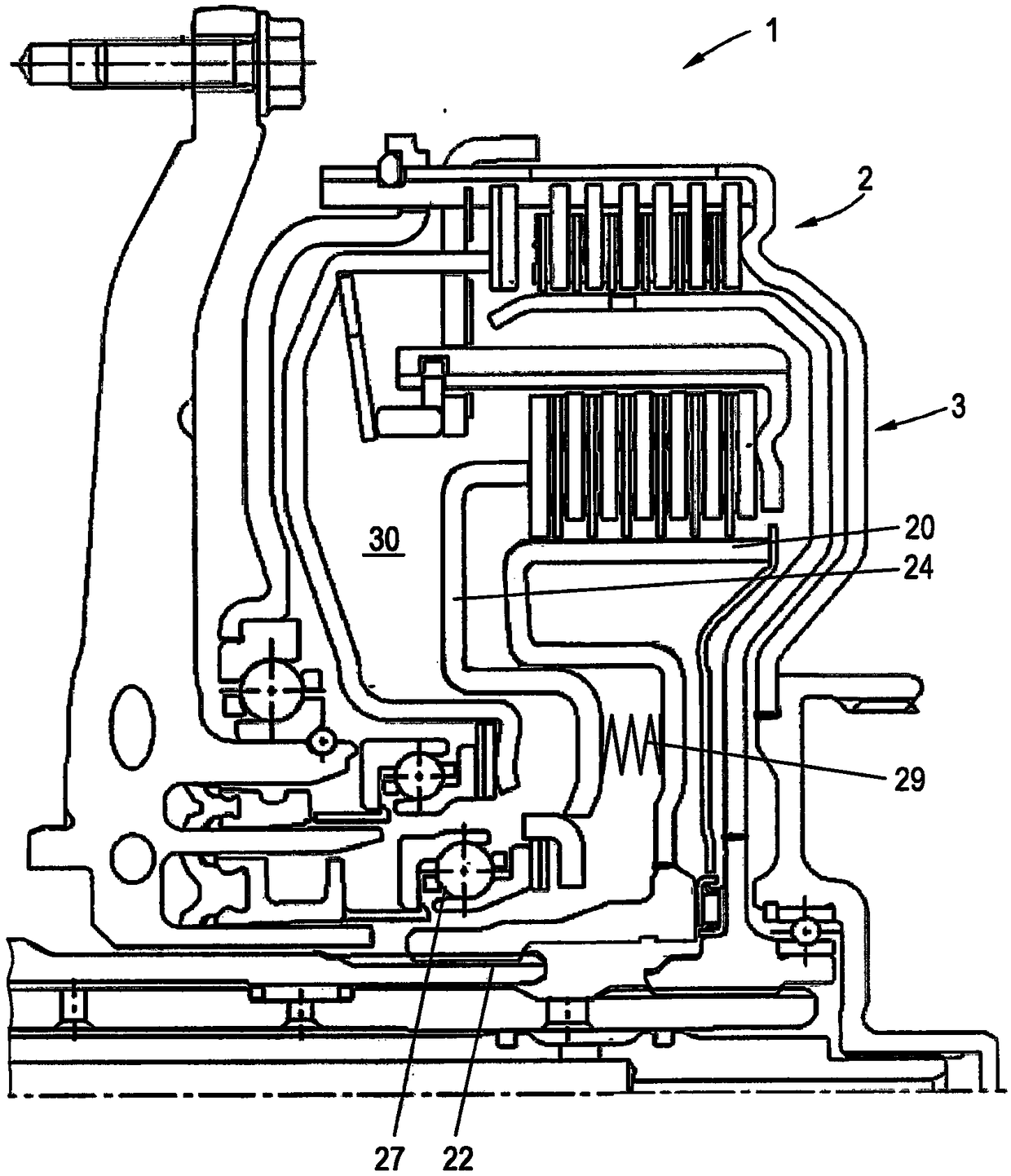
[0021] figure 1 A clutch arrangement 1 according to the invention is shown comprising two subclutches 2 , 3 disposed radially within one another, wherein subclutch 2 is generally referred to as K1 and subclutch 3 is generally referred to as K2 .

[0022] The sub-clutch 2 comprises an outer plate carrier 4 having an outer plate 5, typically a steel plate, arranged thereon. In the exemplary embodiment shown, the outer plate carrier 4 is arranged on a drive element 6 (for example a motor output shaft) and is thus actively driven, for example by an internal combustion engine.

[0023] The sub-clutch 2 also includes an inner plate support 7 on which a plurality of inner plates 8 are arranged, usually friction plates provided with friction linings on both sides. In the exemplary embodiment shown, the inner disc carrier 7 is connected to an output element 9 , for example a transmission shaft or hub or the like leading to the transmission input. The inner disc carrier is decoupled f...


PUM


Abstract

The invention relates to a clutch device comprising two sub-clutches (2, 3) having a common torque input element on the drive side and transmitting torque on the driven side to two separate output elements, and The sub-clutches respectively comprise an outer plate holder (4, 17) having an outer piece (5, 26) and an inner piece holder (7, 20) having an inner piece (8, 21) and an axially movable operating element ( 11, 24), by means of the actuating element, the set of sheets respectively formed by the outer piece and the inner piece (5, 8, 26, 21) can be pressed, wherein at least one sub-clutch(2, 3) The actuating elements (11, 24) are arranged in a rotatable manner on the driven side.

Description

technical field [0001] The invention relates to a clutch arrangement comprising two partial clutches which have a common torque input element on the drive side and transmit torque on the driven side to two independent output elements, and which Each includes an outer disk carrier with an outer disk and an inner disk carrier with an inner disk, as well as an axially movable actuating element, by means of which the disk packs, each composed of the outer disk and the inner disk, can be pressed together. Background technique [0002] Such a clutch arrangement comprising two partial clutches is often also referred to as a double clutch. The two sub-clutches each have an outer plate carrier and an inner plate carrier, whose outer plate and inner plate form a plate pack that can be pressed together by an axially movable actuating element. The two outer plate carriers are, for example, coupled on the drive side to a common drive element (for example a motor output shaft). In this ...

Claims


Application Information

Patent Timeline
Patent Type & Authority Applications(China)
IPC IPC(8): F16D21/06F16D25/08F16D25/10F16D13/52
CPCF16D13/52F16D21/06F16D25/08F16D25/10F16D2021/0661F16D25/082
Inventor H·布切尔
Owner SCHAEFFLER TECH AG & CO KG
Why Eureka
Try Eureka