
Concealed seal floor drain

A sealed and hidden technology, applied in waterway systems, drainage structures, water supply devices, etc., can solve the problems of residents' daily troubles, inconvenient use, slow drainage, etc., and achieve the effect of improving drainage efficiency and avoiding odor backflow.

Active Publication Date: 2018-12-07
绵阳鹏志远科技有限公司
View PDF7 Cites 0 Cited by
  • Summary
  • Abstract
  • Description
  • Claims
  • Application Information

AI Technical Summary

Problems solved by technology

[0002] Existing waterproof floor drains need to manually open the cover plate and filter screen, and then manually cover the cover plate and filter screen after dehydration. During the dehydration process, the cover plate and filter screen are easily lost, because there is water on the surface of the cover plate and filter screen. , and the seal between the dehydration pipe and the sewer is not good, the water will inevitably leak around the floor drain during the whole dehydration process, and the floor drain cover is easy to turn up when not in use, causing the sewer smell to flow back, which brings troubles to residents in daily life. Nowadays, floor drains are often installed in uncommonly used places such as living rooms and bedrooms, which is convenient for residents to live and use. However, the existing waterproof floor drains are set to be raised or sunken on the ground, and cannot be installed in bedrooms or living rooms, which will cause a lot of inconvenience in use. In addition, the existing waterproof floor drain cannot fully open the opening when it is opened, and there is a problem of slow drainage

Method used


Image

  • Concealed seal floor drain
  • Concealed seal floor drain
  • Concealed seal floor drain

Examples


Embodiment 1

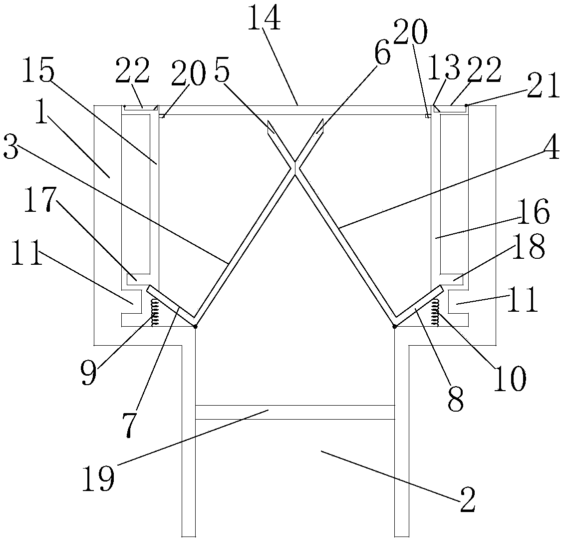
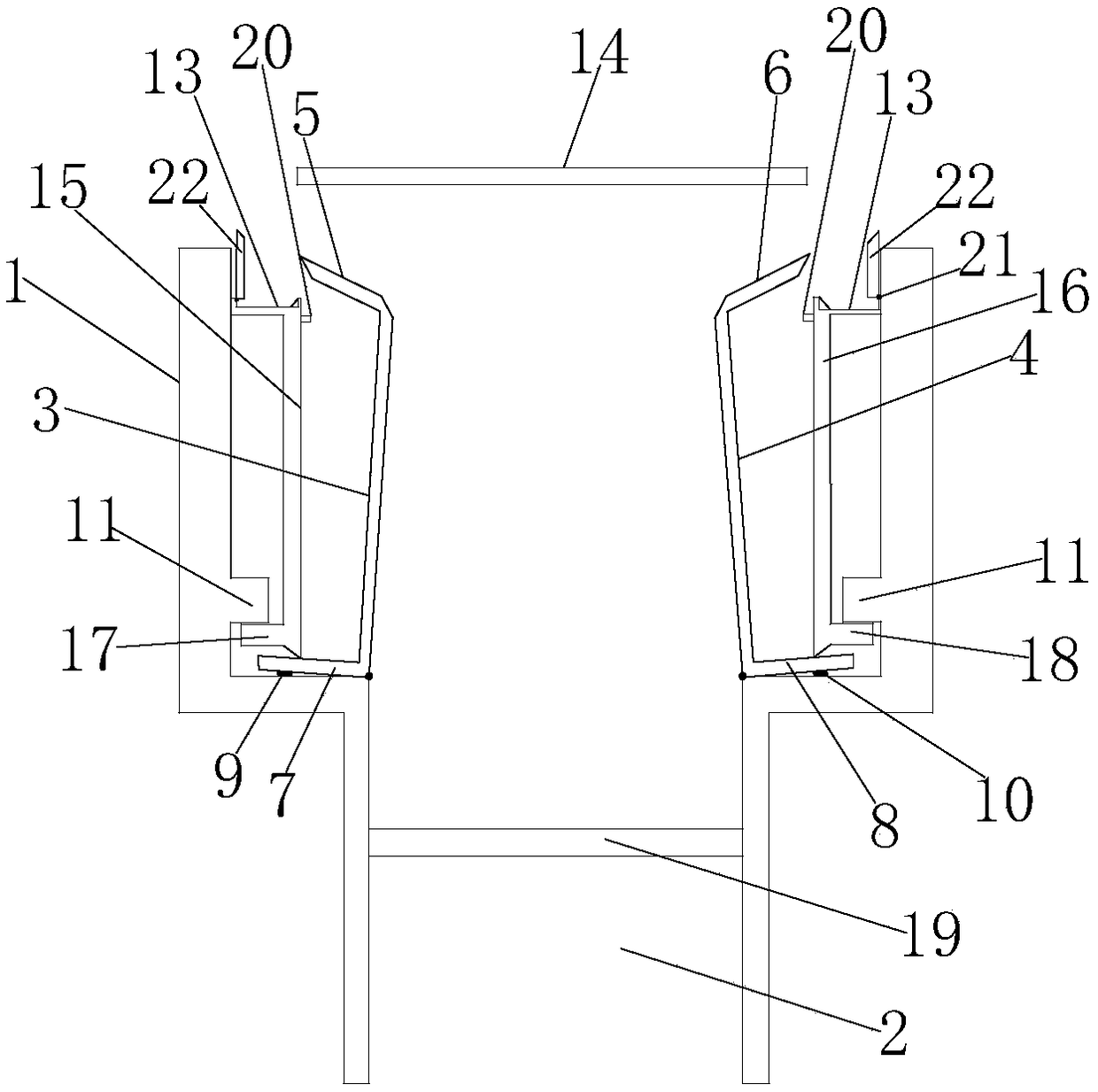
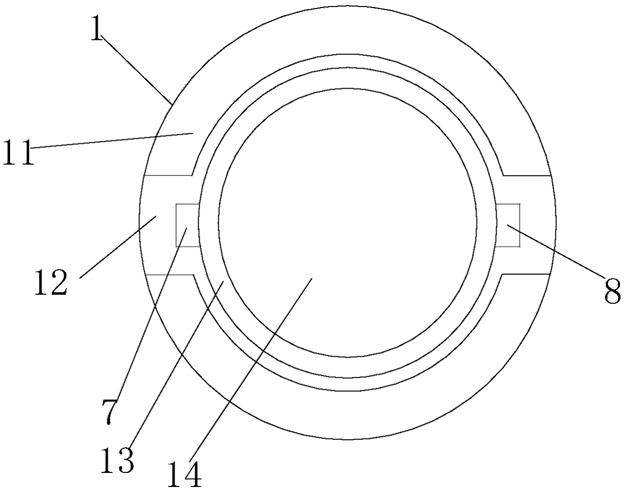
[0029] like Figure 1 to Figure 3As shown, a concealed sealed floor drain includes a base 1, the base 1 is a barrel-shaped structure without a cover, a through hole 2 is arranged at the bottom of the base 1, a filter screen 19 is arranged in the through hole 2, and the through hole 2 is provided with a sealing ring, and the base 1 is provided with a first rotating structure and a second rotating structure inside, and the first rotating structure includes a first rotating main plate 3, a first rotating sub-plate 5 and a first rotating rod 7, The second rotating structure includes a second rotating main board 4, a second rotating sub-board 6, and a second rotating rod 8. The length of the first rotating main board 3 and the second rotating main board 4 is equal to the height of the base 1, so The right end of the first rotating main board 3 is in contact with the left end of the second rotating main board 4 to form a first vertebral body structure, the bottom surface of the firs...

Embodiment 2

[0031] Based on the above embodiment, this embodiment implements the working process when the device of the above embodiment does not need to be closed, such as figure 1 As shown, when not in use, the first pressure spring 9 and the second pressure spring 10 remain in their original state, and the included angle between the first rotating rod 7 and the second rotating rod 8 and the base 1 is naturally kept at 30 degrees, and the first The right end of the rotating main board 3 is in natural contact with the left end of the second rotating main board 4, the first pressing rod 15 is in natural contact with the first rotating rod 7, the second pressing rod 16 is in natural contact with the second rotating rod 8, the pressing ring 13 and the gland The structure composed of 14 is naturally placed on the base 1 through the limit block 20, and the handle 22 matched with the groove is closed by the hinge 21 on the edge of the groove on the pressing ring 13 to prevent it from being in t...

Embodiment 3

[0035] Based on the above-mentioned embodiment, this embodiment implements the working process when the device of the above-mentioned embodiment is used and opened, such as figure 2 As shown, when the use is opened, first turn the handle 22 out of the groove, press the handle 22 downward, drive the pressure ring 13, and then drive the first pressure rod 15 and the second pressure rod 16 to move downward, The first pressing rod 15 drives the first rotating rod 7 to move downward, the second pressing rod 16 drives the second rotating rod 8 to move downward, the first pressure spring 9 and the second pressure spring 10 are compressed, and then drive the first rotating main board 3 and the second rotating main plate 4 are far away from opening, and the first rotating sub-plate 5 and the second rotating sub-plate 6 are away from opening, and the first rotating sub-plate 5 and the second rotating sub-plate 6 will push up the gland 14 at the same time. When the pressure spring 9 and...


PUM


Abstract

The invention discloses a concealed seal floor drain. The concealed seal floor drain comprises a base, a first rotating main board, a second rotating main board, a first rotating auxiliary board, a second rotating auxiliary board, a first rotating rod and a second rotating rod; a first pressure spring is arranged between the first rotating rod and the bottom of the base, a second pressure spring is arranged between the second rotating rod and the bottom of the base, and a compression ring and a gland are arranged on the top of the base separately. According to the concealed seal floor drain, the problem that when an ordinary floor drain is used, parts are likely to be lost can be prevented in application, the floor drain is opened in use and can be automatically closed when not in use, andsewer odor backflow is avoided; meanwhile, the overall design is concealed, the floor drain can be arranged in occasions not in common use conveniently, and normal use of the occasions is not affected when the floor drain is not used.

Description

technical field [0001] The invention relates to a floor drain, in particular to a concealed sealed floor drain. Background technique [0002] Existing waterproof floor drains need to manually open the cover plate and filter screen, and then need to manually cover the cover plate and filter screen after dehydration. , and the seal between the dehydration pipe and the sewer is not good, water will inevitably leak around the floor drain during the whole dehydration process, and the floor drain cover is easy to flip up when not in use, causing the sewer smell to flow back, which brings troubles to residents in daily life. Nowadays, floor drains are often installed in uncommonly used places such as living rooms and bedrooms, which can be convenient for residents to live and use. However, the existing waterproof floor drains will be set to protrude or sag on the ground, and cannot be installed in bedrooms or living rooms, which will cause a lot of inconvenience in use. In additio...

Claims


Application Information

Patent Timeline
Patent Type & Authority Applications(China)
IPC IPC(8): E03F5/04
Inventor 梁静
Owner 绵阳鹏志远科技有限公司
Learn More