A microfluidic valve and a microfluidic control method thereof

A microfluidic and microfluidic technology, applied in valve devices, mechanical equipment, engine components, etc., can solve the problem of inability to have both microfluidic low-cost, accurate flow and on-off operation control functions, inability to use fluids, and inability to use fluids. Real-time motion and cut-off control, etc., to achieve the effects of easy miniaturization integration, low threshold pressure, and wide application value

Active Publication Date: 2019-09-10
HOHAI UNIV CHANGZHOU
View PDF5 Cites 0 Cited by
  • Summary
  • Abstract
  • Description
  • Claims
  • Application Information

AI Technical Summary

Problems solved by technology

However, passive flow regulating valves cannot be used for real-time movement and cut-off control of fluids, so they cannot be used in applications where fluids often require on-off control
[0005] In summary, the existing microfluidic valves cannot combine the low cost, precise flow and on-off operation control functions of microfluidics. It is necessary to develop microvalves with new structures to meet the above-mentioned microfluidic operation control requirements.

Method used


Image

  • A microfluidic valve and a microfluidic control method thereof
  • A microfluidic valve and a microfluidic control method thereof
  • A microfluidic valve and a microfluidic control method thereof

Examples


Embodiment Construction

[0036] Preferred embodiments of the present invention will be described below in conjunction with the accompanying drawings. It should be understood that the preferred embodiments described here are only used to illustrate and explain the present invention, and are not intended to limit the present invention.

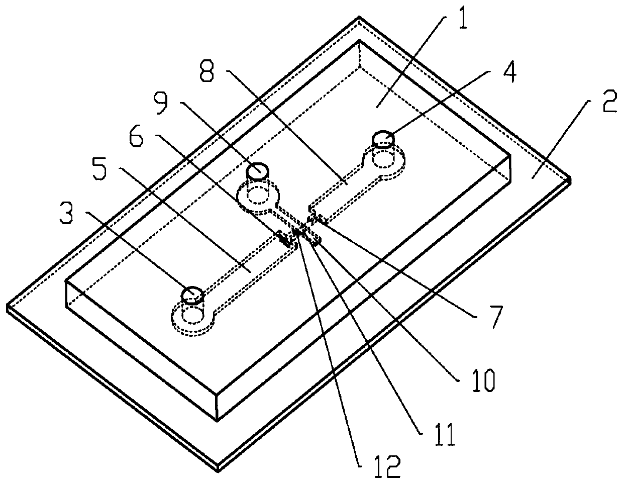
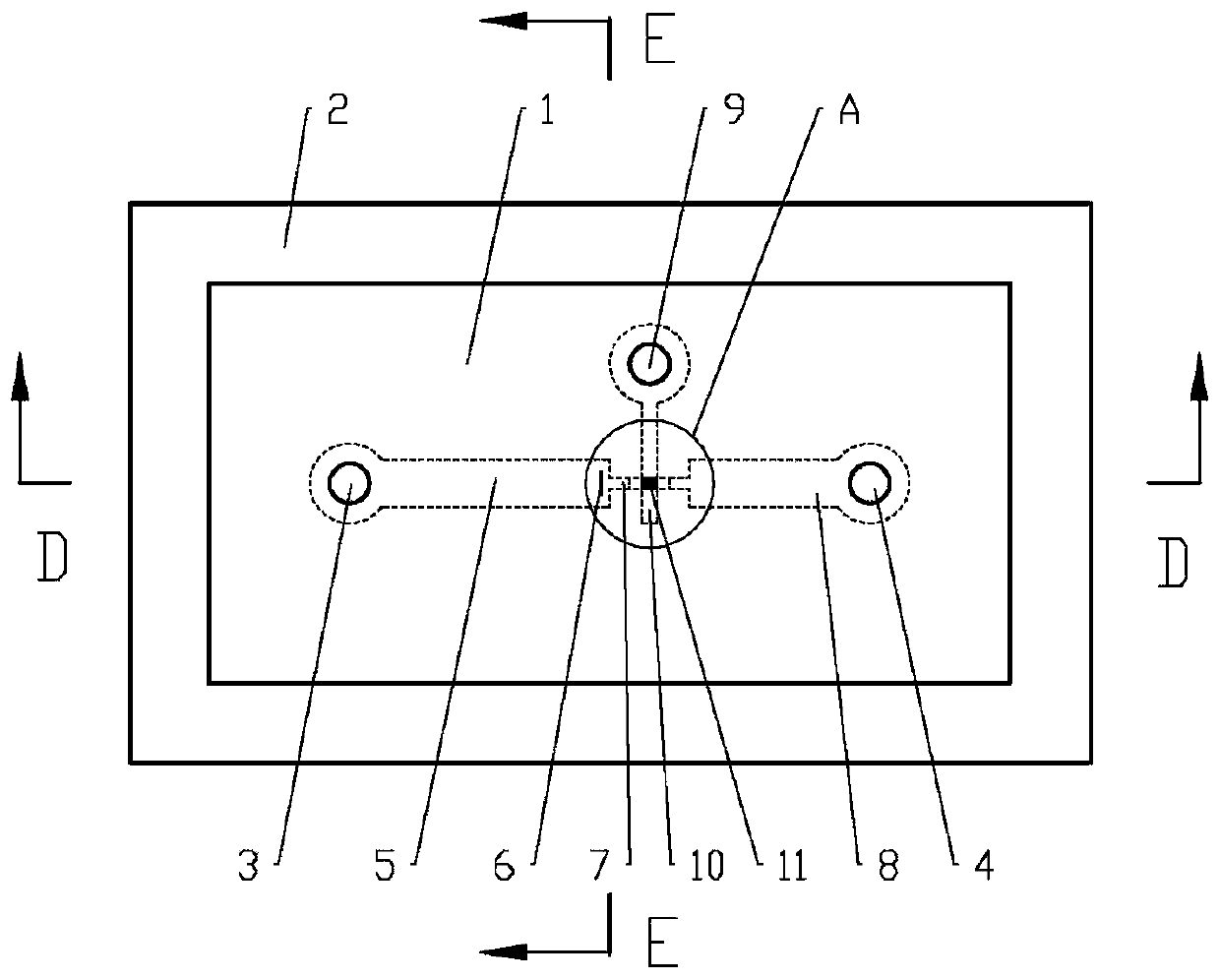
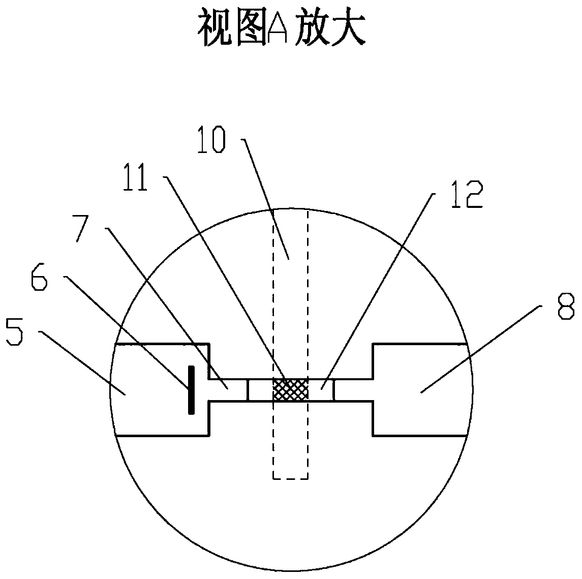
[0037] A microfluidic control valve in the present invention uses the lateral deformation of the flow regulating film 6 in the inlet main channel 5 to be impacted by the liquid to adjust the microfluid entering the contraction channel 7, and automatically adjusts the flow resistance of the microvalve and compensates The change of inlet liquid pressure achieves the purpose of precise control of microfluidic flow. At the same time, the cut-off film 11 in the control flow channel 10 is subjected to the pressure of the compressed gas to make the film elastically deform, close to and close the curved surface flow channel 12, and realize the cut-off control of the microfluid. ...


PUM


Abstract

The invention relates to a microfluidic valve. The microfluidic valve comprises a liquid inlet, an inlet runner, a shrinkage runner, a curved runner, an outlet runner, a liquid outlet, a gas inlet anda control runner. Microfluids flow in from the liquid inlet, pass through the inlet runner, the shrinkage runner, the curved runner and the outlet runner in sequence, and are drained by the liquid outlet; a current adjusting film is arranged in the inlet runner near the shrinkage runner; the microfluids extrude the current adjusting film to enable the flowing resistance of the valve to compensatethe flowing pressure so as to realize automatic and precise flow control of the fluids; a closure film is arranged between the control runner and the curved runner; compressed gas enters the controlrunner by the gas inlet; and the curved runner is totally closed through extrusion of the closure film to realize movement and stop control of the fluids. The microfluidic valve is small in size, easyto integrate, low in threshold pressure and precise in flow control, and can meet the integration demands of most microdriving devices.

Description

technical field [0001] The invention relates to a fluid precision control valve and a control method for fluid movement thereof, in particular to a microfluid control valve and a microfluid control method. Background technique [0002] With the development of micro-nano manufacturing technology, microfluidic valves have played an important role as micro-scale control elements in the fields of structure and chemical biology, gene sequencing, and single-cell analysis. Because microfluidic valves can precisely regulate the flow of microfluids and meet the requirements of precise microfluidic control, they have a wide range of application requirements in the fields of precise drug delivery systems, nucleic acid detection, and cell sorting. [0003] Existing microfluidic valves are mainly divided into active flow regulating valves and passive flow regulating valves. The active flow regulating valve mainly adjusts the liquid flow by adding control elements, such as using pneumati...

Claims


Application Information

Patent Timeline
Patent Type & Authority Patents(China)
IPC IPC(8): F16K99/00
Inventor 张鑫杰
Owner HOHAI UNIV CHANGZHOU
Why Eureka
Try Eureka