Mixer and a method for operating same

A technology of mixers and injectors, applied in the direction of combustion methods, combustion chambers, combustion equipment, etc., can solve different problems

Active Publication Date: 2018-12-07
ANSALDO ENERGIA SWITZERLAND AG
View PDF15 Cites 0 Cited by
  • Summary
  • Abstract
  • Description
  • Claims
  • Application Information

AI Technical Summary

Problems solved by technology

[0013] However, the mass flow fluctuation amplitude of injected air at different axial positions of the mixer may be different due to the acoustic mode inside the mixer

Method used


Image

  • Mixer and a method for operating same
  • Mixer and a method for operating same
  • Mixer and a method for operating same

Examples


Embodiment Construction

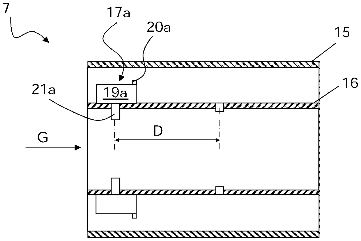
[0049] Referring to the figures, the mixer 7 is shown. The mixer 7 includes a housing 15 , a tube 16 within the housing 15 , a first injector 17a and a second injector 17b for injecting a fluid (eg, possibly cooled compressed air from a compressor) into the tube 16 ; The fluid is injected by the first injector 17a and the second injector 17b in a fluctuating mass flow.

[0050] As described below, the first injector 17a and the second injector 17b may be provided around the outer circumference of the tube 16 and may lead to the tube at one or more points.

[0051] The first injector 17a and the second injector 17b have a distance D such that the mass flow of fluid injected through the first injector 17a reaches the second injector in reverse phase to the mass flow of fluid injected through the second injector 17b 17b. For example, when the first injector 17a injects a large fluid mass flow, the large fluid mass flow travels axially through the tube 16 and reaches the second ...


PUM


Abstract

The mixer (7) comprises a housing (15), a duct (16) within the housing (15), at least a first injector (17a) and a second injector (17b) for injecting a fluid having a fluctuating mass flow into the duct (16). The first injector (17a) and the second injector (17b) are at a distance (D) such that the fluid mass flow injected through the first injector (17a) reaches the second injector (17b) in phase opposition with the fluid mass flow injected through the second injector (17b). The first and the second injectors (17a, 17b) are configured and arranged for injecting a mass flow having substantially the same fluctuation amplitude.

Description

[0001] claim of priority [0002] This application claims priority to European Patent Application No. 17172854.6, filed on May 24, 2017, the disclosure of which is incorporated herein by reference. technical field [0003] The present invention relates to a mixer and a method for operating the mixer. [0004] In particular, the mixer is part of a gas turbine, eg a gas turbine of a power plant. Background technique [0005] figure 1 An example of a gas turbine is schematically shown; the gas turbine 1 has a compressor 2 , a first combustion chamber 3 , a second combustion chamber 4 and a turbine 5 . A high pressure turbine may be provided between the first combustion chamber 3 and the second combustion chamber 4 . During operation, the air is compressed at the compressor 2 and used to combust fuel in the first combustion chamber 3; the hot gases (possibly partially expanded in the high pressure turbine) are then sent to the second combustion chamber 4 where, Another fue...

Claims


Application Information

Patent Timeline
Patent Type & Authority Applications(China)
IPC IPC(8): F23R3/28
CPCF23R3/286F23R2900/00013
Inventor A.斯卡尔帕托B.许曼斯M.博蒂恩F.格宁L.泰沃庄希拉雷斯N.K.阿卢里
Owner ANSALDO ENERGIA SWITZERLAND AG
Why Eureka
Try Eureka