A smart home matcher

A smart home and matching device technology, applied in the direction of instruments, simulators, program control, etc., can solve the problems that household appliances cannot be controlled by remote control and inconvenient operation, and achieve the effect of full intelligence and simple overall structure

Active Publication Date: 2021-04-23
广州市得腾技术服务有限责任公司
View PDF5 Cites 0 Cited by
  • Summary
  • Abstract
  • Description
  • Claims
  • Application Information

AI Technical Summary

Problems solved by technology

[0002] Among the existing household appliances, there are still a large number of household appliances that cannot be controlled remotely, such as washing machines, microwave ovens and other equipment, and even if remote control devices are added to these household appliances, it will be difficult to control them through a The device controls all the household appliances in the home (unless all the devices are of the same brand), so that people may need multiple control devices or download multiple control APPs to control the household appliances when controlling the home, which is very inconvenient to operate

Method used


Image

  • A smart home matcher
  • A smart home matcher
  • A smart home matcher

Examples


Embodiment 1

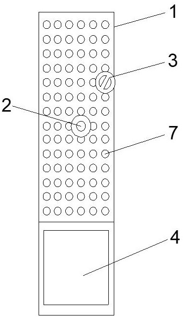
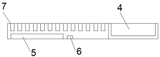
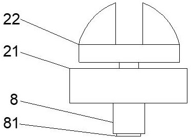
[0043] like figure 1 and figure 2 as well as Figure 9 As shown, a smart home matching device includes a base plate 1, a button part 2 for pressing a button, a knob part 3 for turning a knob, a control panel 4 installed on the base plate 1, and a The central processing unit 5 is connected to the timer 6, and the central processing unit 5 is connected to the timer 6 and the control panel 4 for signals, and a plurality of first chambers 7 are distributed on the base plate 1, and the button part 2 and the knob part 3 are arranged There is an adapter 8 that matches the first cavity 7, and by placing the adapter 8 in the first cavity 7, the central processing unit 5 is electrically and / or signally connected to the button portion 2 and the knob portion 3 to control The opening and closing of the button part 2 and the knob part 3. The adapter 8 is preferably cylindrical. The control panel 4 is preferably a touch screen.

[0044] Preferably, as Figure 7 As shown, the first cav...

Embodiment 2

[0064] Different from Embodiment 1, the button part 2 and / or the knob part 3 is provided with a micro control unit 13, the first cavity 7 is provided with a first data transmission interface 72, and the adapter 8 is provided with a There is a second data transmission interface 82 matched with the first data transmission interface 72 , the first data transmission interface 72 is connected to the central processing unit 5 , and the second data transmission interface 82 is connected to the micro control unit 13 . The micro-control unit 13 is connected with the first air cylinder 23 or the rotating air cylinder 33 for signals. After the central processing unit 5 transmits the control information to the micro control unit 13 through the first data transmission interface 72 and the second data transmission interface 82 , the micro control unit 13 then controls the rotary cylinder 33 or the first cylinder 23 .

Embodiment 3

[0066] like figure 1 and 10 A smart home matcher is shown, including a base plate 1, a button portion 2, a knob portion 3, a control panel 4 installed on the base plate 1, a central processing unit 5 and a timer 6 arranged in the base plate 1, the central processing unit The unit 5 is signal-connected with the timer 6 and the control panel 4. There are several first cavities 7 distributed on the bottom plate 1. The button part 2 and the knob part 3 are provided with adapters 8 that match the first cavities 7. , by placing the adapter 8 in the first cavity 7, so that the button part 2 and the knob part 3 are electrically connected and / or signal connected with the central processing unit 5, and the central processing unit 5 controls the expansion and contraction of the button part 2 and the control knob through the signal Part 3 rotates. The adapter 8 is preferably cylindrical.

[0067] Preferably, the smart home matching device further includes several button parts 2 and kno...


PUM


Abstract

The invention discloses a smart home matcher, which comprises a base plate, a button part for pressing a button, a knob part for turning a knob, a control panel installed on the base plate, a central processing unit and a timer arranged in the base plate The central processing unit is connected to the timer and the control panel for signals, and there are several first cavities distributed on the bottom plate, and the button part and the knob part are provided with an adapter matching the first cavities. The adapter is placed in the first cavity so that the central processing unit is electrically and / or signally connected to the button part and the knob part to control the opening and closing of the button part and the knob part. The present invention can assemble different button parts and knob parts into the first cavities at different positions according to the models of different household appliances, and can match most of the household appliances without being restricted by brands and models, which is beneficial Realize the full intelligence of household appliances.

Description

technical field [0001] The invention belongs to the field of smart home, and in particular relates to a smart home matcher. Background technique [0002] Among the existing household appliances, there are still a large number of household appliances that cannot be controlled remotely, such as washing machines, microwave ovens and other equipment, and even if remote control devices are added to these household appliances, it will be difficult to control them through a The device controls all the household appliances in the home (unless all the devices are of the same brand), so that people may need multiple control devices or download multiple control APPs to control the household appliances when controlling the home, which is very inconvenient to operate. Contents of the invention [0003] The purpose of the present invention is to provide a smart home matching device for controlling different types of household appliances of different brands. [0004] To achieve the abov...

Claims


Application Information

Patent Timeline
Patent Type & Authority Patents(China)
IPC IPC(8): G05B19/042
CPCG05B19/0423G05B2219/2642
Inventor 杨瑞典
Owner 广州市得腾技术服务有限责任公司
Why Eureka
Try Eureka