Graphical remote monitoring method and system for manual valve

A remote monitoring system and manual valve technology, which is applied to still image data browsing/visualization, valve device, engine components, etc. Monitor the effect and realize the effect of full intelligence

Pending Publication Date: 2021-04-09
国能长源汉川发电有限公司
View PDF0 Cites 0 Cited by
  • Summary
  • Abstract
  • Description
  • Claims
  • Application Information

AI Technical Summary

Problems solved by technology

[0003] However, a large number of manual valves are also used in some equipment or application environments, and the switching status of these manual valves cannot be seen on the automation control software or the computer in the central control room, and it is impossible to remotely monitor the manual valves in a graphical way. To confirm the switch status of the valve, it is very inconvenient to manually search for the relevant work ticket and combine it with on-site inspection.
[0004] At present, there is no method for remote monitoring of manual valves in a graphical way. It is possible to view and monitor the switch status of manual valves at the remote end of automation control, and improve the remote monitoring effect of manual valves.

Method used


Image

  • Graphical remote monitoring method and system for manual valve
  • Graphical remote monitoring method and system for manual valve
  • Graphical remote monitoring method and system for manual valve

Examples


Embodiment 1

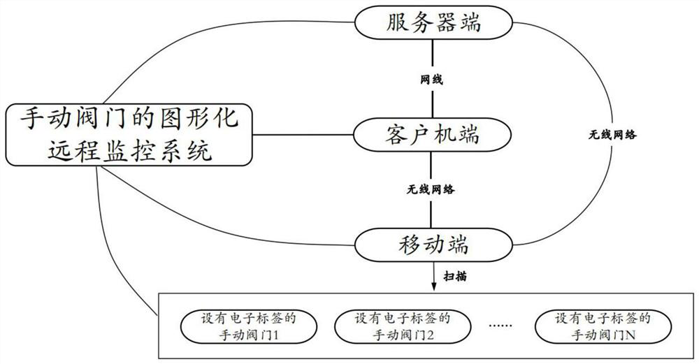
[0033] Embodiment one, as figure 1 As shown, a graphical remote monitoring system for manual valves includes a server end, a client end, a mobile end and at least one manual valve with an electronic label; the client end is connected to the server end and the mobile end respectively terminal communication connection, the server terminal and the mobile terminal communication connection;

[0034] The server end is used to: store the valve system diagram and at least one manual valve and valve electronic label information;

[0035] The client side is used for:

[0036] Obtain the valve system diagram, the initial switching status of all manual valves and the valve electronic label information from the server, generate an operation ticket according to the valve system diagram and all valve electronic label information and send it to the mobile terminal; wherein, The operation ticket contains one-to-one corresponding local operation tasks for each target manual valve;

[0037] T...

Embodiment 2

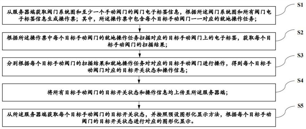
[0082] Embodiment two, based on embodiment one, such as figure 2 As shown, this embodiment also discloses a graphical remote monitoring method for manual valves, using the graphical remote monitoring system for manual valves in Embodiment 1 to remotely monitor manual valves, including the following steps:

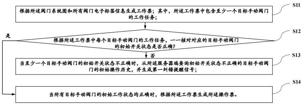
[0083] S1: Obtain the valve system diagram and the valve electronic label information of at least one manual valve from the server, and generate an operation ticket according to the valve system diagram and all valve electronic label information; wherein, the operation ticket contains a A corresponding local operation task;

[0084] S2: Scan the electronic label on the corresponding target manual valve according to the local operation task of each target manual valve in the operation ticket, and obtain the scanning result of each target manual valve;

[0085] S3: Operate the corresponding target manual valve according to the scanning result of each target manual valve and...


PUM


Abstract

The invention relates to a graphical remote monitoring method and system for a manual valve. The graphical remote monitoring system comprises a server side, a client side, a mobile side and at least one manual valve provided with an electronic tag. The client side obtains a valve system diagram and valve electronic tag information of all the manual valves from the server side, generates an operation order and sends the operation order to the mobile side; the mobile terminal receives the operation order and scans the electronic tag on the target manual valve according to the operation order to obtain a scanning result; when each target manual valve is operated according to the scanning result of each target manual valve and the on-site operation task, a corresponding target on-off state and operation information are obtained and uploaded to the server side; and the client performs graphical display according to a preset graphical display method and the target on-off state of each target manual valve. According to the invention, the on-off state of the manual valve can be checked and monitored graphically at the remote client.

Description

technical field [0001] The invention relates to the technical field of automatic control and remote monitoring, in particular to a graphical remote monitoring method and system for manual valves. Background technique [0002] In the process of industrial production, automatic centralized remote control has been realized in many places. The important valves adopt automatic valve control mode (including electric or pneumatic control mode), which can realize remote switch control and opening adjustment of these switches, and Graphical automatic valve switch status can be seen on the central control room computer. [0003] However, a large number of manual valves are also used in some equipment or application environments, and the switching status of these manual valves cannot be seen on the automation control software or the computer in the central control room, and it is impossible to remotely monitor the manual valves in a graphical way. To confirm the switch status of the v...

Claims


Application Information

Patent Timeline
Patent Type & Authority Applications(China)
IPC IPC(8): G06K19/07G06K19/06G06F16/54G06K7/10G06Q10/00F16K37/00
CPCF16K37/0083G06K7/10009G06K19/06037G06K19/07G06Q10/20G06F16/54
Inventor 吴剑张海军梅海龙刘超辉樊明瑾陈兴李威
Owner 国能长源汉川发电有限公司
Why Eureka
Try Eureka