Inter-layer adhesive force testing component

A technology for interlayer adhesion and testing components, which can be used in measuring devices, instruments, and mechanical devices, etc., and can solve the problem that the tensile force cannot be guaranteed to be perpendicular to the surface of the sample to be tested.

Inactive Publication Date: 2018-12-11
ZHANGJIAGANG KANGDE XIN OPTRONICS MATERIAL
View PDF9 Cites 2 Cited by
  • Summary
  • Abstract
  • Description
  • Claims
  • Application Information

AI Technical Summary

Problems solved by technology

[0005] The purpose of the present invention is to provide a kind of interlayer adhesion test assembly, to solve the problem that the pulling force is not guaranteed to be perpendicular to the surface of the sample to be tested in the existing adhesion test

Method used


Image

  • Inter-layer adhesive force testing component
  • Inter-layer adhesive force testing component
  • Inter-layer adhesive force testing component

Examples


Embodiment 1

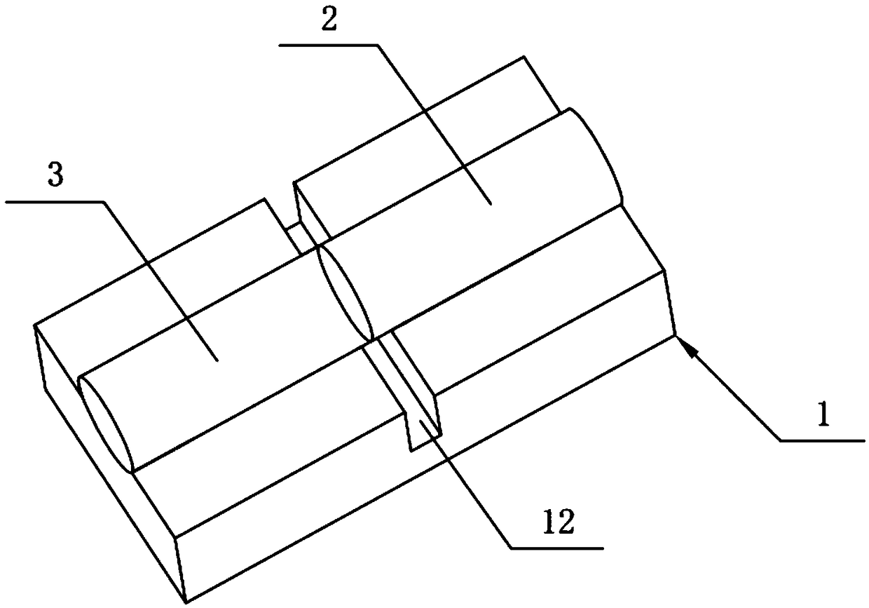
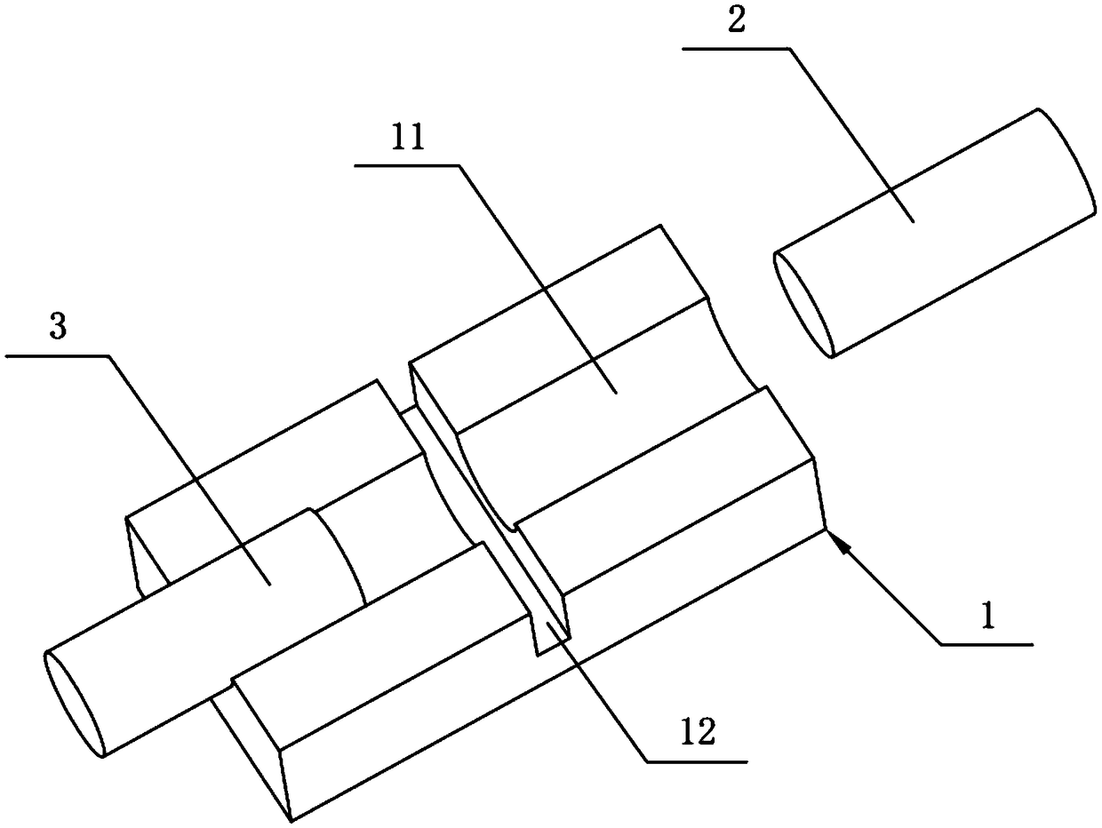
[0030] This embodiment provides a kind of interlayer adhesion testing assembly, such as figure 1 and figure 2 As shown, the interlayer adhesion test assembly includes a base 1, a first pulling column 2 and a second pulling column 3, wherein:

[0031] The above-mentioned base 1 may be in the shape of a rectangular block, and a sliding groove 11 is provided on the base 1 along the length direction, and the sliding groove 11 is used for placing the first pulling column 2 and the second pulling column 3 . Specifically, the cross-sectional shape of the chute 11 is adapted to the cross-sectional shape of the first drawing column 2 and the second drawing column 3. For example, in this embodiment, the cross-sectional shape of the chute 11 can be a semicircle, while the first The cross-sectional shape of the drawing column 2 and the second drawing column 3 is circular. The cross-sectional shape of the chute 11 may also be rectangular, and the cross-sectional shapes of the first pull...

Embodiment 2

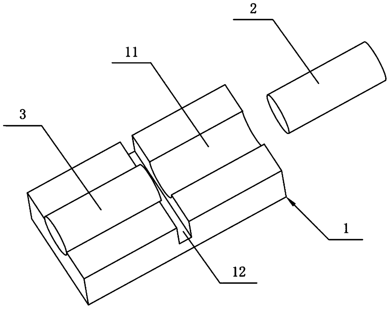
[0041] The difference between the present embodiment and the first embodiment lies in that the second pulling column 3 of the interlayer adhesion testing assembly of the present embodiment is fixed on the base 1 , and the second pulling column 3 is not connected with a tensile force detection element. Specifically, refer to image 3 , the second pulling column 3 of the interlayer adhesion test assembly of this embodiment is fixedly arranged at the chute 11 , and only the first pulling column 2 is connected with a tension detection piece. The rest of the structure of the interlayer adhesion testing component of this embodiment is the same as that of Embodiment 1, and will not be repeated here.

[0042]When the above-mentioned interlayer adhesion test assembly of the present embodiment is in use, first the first pulling column 2 is placed on the chute 11, and then one of the film layers or the base layer of the sample to be tested is adhered to the first pulling column 2. On th...


PUM


Abstract

The invention belongs to the technical field of adhesive force testing, and discloses an inter-layer adhesive force testing component. The component comprises a pedestal, a first drawing column and asecond drawing column, wherein the first drawing column is arranged on the pedestal in a sliding mode; the second drawing column is arranged on the pedestal; two opposite end faces of the first drawing column and the second drawing column can be respectively adhered to two sides of a to-be-tested sample part, and the sliding direction of the first drawing column is vertical to the end face, to which the to-be-tested sample part is adhered, of the first drawing column. The first drawing column and/or the second drawing column are/is driven by drawing equipment such as a drawing machine to movein an axial direction so as to enable the first drawing column or the second drawing column to apply drawing force to the to-be-tested sample part, so that the inter-layer adhesive force testing to the to-be-tested sample part is realized. Moreover, the structure can guarantee that the drawing force is applied in the inter-layer direction which is vertical to the to-be-tested sample part, and thenthe inter-layer axial adhesive force testing of the to-be-tested sample part is realized.

Description

technical field [0001] The invention relates to the technical field of adhesion testing, in particular to an interlayer adhesion testing component. Background technique [0002] The adhesive force of existing test film layer usually adopts adhesive tape method, and adhesive tape method is to adhere the viscous surface of a kind of specific adhesive tape on the film layer surface of sample to be tested, tape is pasted flat, removes all air bubbles, and then Peel off the adhesive tape with a steady pulling force. If the film layer is not peeled off the base layer of the sample to be tested, it means that the film layer has good adhesion. [0003] Although the adhesive tape method can indicate the adhesion of the film layer to a certain extent, the pulling force applied by it cannot be guaranteed to be perpendicular to the surface of the film layer, and the adhesion of the test is not the true sense of the film layer and the film layer of the sample to be tested. Axial adhesio...

Claims


Application Information

Patent Timeline
Patent Type & Authority Applications(China)
IPC IPC(8): G01N19/04
CPCG01N19/04
Inventor 曹英杰李守军
Owner ZHANGJIAGANG KANGDE XIN OPTRONICS MATERIAL
Why Eureka
Try Eureka