
Magnetic ring fixing device and electrical box

A technology for fixing devices and electrical boxes, used in magnetic field/electric field shielding, electrical components, screening enclosures, etc.

Active Publication Date: 2020-04-28
GREE ELECTRIC APPLIANCES INC
View PDF12 Cites 0 Cited by
  • Summary
  • Abstract
  • Description
  • Claims
  • Application Information

AI Technical Summary

Problems solved by technology

The traditional magnetic ring is often tightly wound with the required wire first, and then directly suspended and fixed around the filter board by ordinary wire tie or branch wire tie. This fixing method cannot effectively limit and fix the magnetic ring , when the whole machine is running normally, the magnetic ring will shake in the electrical box, and there is a risk of damaging components and breaking wires
In order to solve the shaking of the magnetic ring, there is a risk of crashing the components and breaking the wire, the magnetic ring can be fixed in the magnetic ring shell through the magnetic ring box, but because the power cord needs to be wrapped around the magnetic ring, this fixing method will be difficult to wind Thicker power cord; the magnetic ring can also be limited by the limit rib, but the limit rib is too low to effectively limit the lateral movement of the magnetic ring, resulting in the loosening of the magnetic ring
[0003] In view of the limitations of the above-mentioned magnetic ring fixing methods and the requirement that the magnetic ring needs to be wound with multi-layer power cords, no effective solution has been given in the prior art

Method used


Image

  • Magnetic ring fixing device and electrical box
  • Magnetic ring fixing device and electrical box
  • Magnetic ring fixing device and electrical box

Examples


Embodiment 1

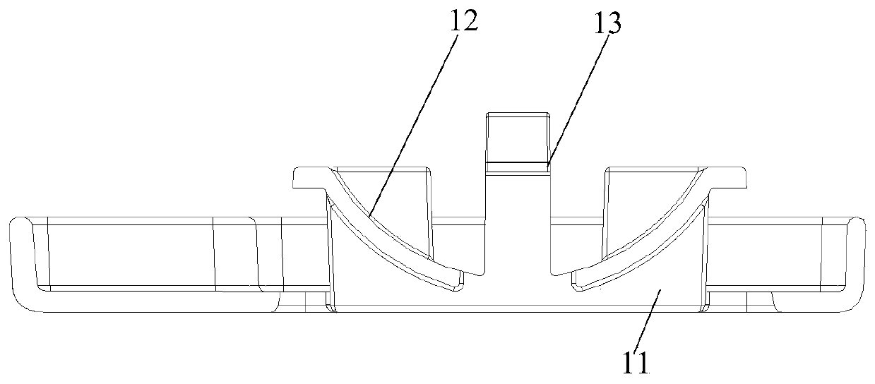
[0026] This embodiment provides a magnetic ring fixing device, such as figure 1 As shown, the magnetic ring fixing device includes a fixing surface 11, an arc-shaped positioning surface 12 arranged on the fixing surface 11, and two engaging parts 13 located on both sides of the arc-shaped positioning surface and oppositely arranged (Fig. Only one clamping part is shown in the figure); the two clamping parts 13 are used to clamp the inner circle of the magnetic ring, so as to fix and limit the magnetic ring on the arc-shaped positioning surface. Wherein the clamping part may be a buckle.

[0027] The arc-shaped positioning surface 12 may be one arc-shaped surface, or may be composed of two arc-shaped surfaces with gaps as shown in the figure. That is to say, in some embodiments, a gap is provided at the lowest end of the arc-shaped positioning surface relative to the fixing surface, and the two locking components are located on both sides of the gap.

[0028] In this embodime...

Embodiment 2

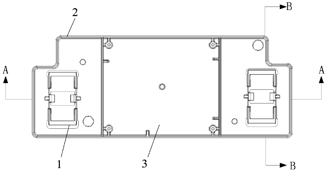
[0035] This embodiment provides an electrical box, such as Figure 1-Figure 6 As shown, the electrical box includes a housing 2, a main board 3 arranged inside the housing, and a magnetic ring fixing device 1 arranged on both sides of the main board, and the magnetic ring fixing device is any one of the first embodiment. The magnetic ring fixing device described in the item.

[0036] Wherein, the magnetic ring fixing device and the housing are integrally formed.

[0037] When this embodiment is actually implemented, reference may be made to Embodiment 1, and it has corresponding technical effects, so details are not repeated here.


PUM


Abstract

The invention relates to the field of electrical equipment, in particular to a magnetic ring fixing device and an electrical box. The invention provides a magnetic ring fixing device and an electric appliance box, so as to realize the limiting fixing of the magnetic ring at least under the requirement that the magnetic ring winds the power supply wire. The magnetic ring fixing device comprises a fixing surface, an arc-shaped positioning surface arranged on the fixing surface, and two clamping parts arranged on two sides of the arc-shaped positioning surface and opposite to each other. The twoengaging parts are used for engaging the inner circle of the magnetic ring so as to fix and limit the magnetic ring to the arc-shaped positioning surface.

Description

technical field [0001] The invention relates to the field of electrical equipment, in particular to a magnetic ring fixing device and an electrical box. Background technique [0002] As an important electrical component of the filter board in the electrical box, the magnetic ring is indispensable in all kinds of electrical boxes. The traditional magnetic ring is often tightly wound with the required wire first, and then directly suspended and fixed around the filter board by ordinary wire tie or branch wire tie. This fixing method cannot effectively limit and fix the magnetic ring , When the whole machine is running normally, the magnetic ring will shake in the electrical box, and there is a risk of damaging components and breaking wires. In order to solve the shaking of the magnetic ring, there is a risk of crashing the components and breaking the wire, the magnetic ring can be fixed in the magnetic ring shell through the magnetic ring box, but because the power cord needs...

Claims


Application Information

Patent Timeline
Patent Type & Authority Patents(China)
IPC IPC(8): H05K9/00
CPCH05K9/0007
Inventor 叶强蔚陈新聪杨爱玲程飞飞
Owner GREE ELECTRIC APPLIANCES INC
Learn More