Vehicle lamp

A technology for lamps and vehicles, applied in the direction of headlights, vehicle parts, lighting devices, etc., can solve the problems of not being able to obtain sufficient reflected light amount, difficult to improve the recognition of forward observation, etc., and achieve the effect of improving the recognition of front observation

Inactive Publication Date: 2018-12-14
KOITO MFG CO LTD
View PDF10 Cites 2 Cited by
  • Summary
  • Abstract
  • Description
  • Claims
  • Application Information

AI Technical Summary

Problems solved by technology

[0011] However, since this reflective region is located at a position that is greatly deviated from the vertical direction of the light emitting surface of the first light emitting element, suffic

Method used


Image

  • Vehicle lamp
  • Vehicle lamp
  • Vehicle lamp

Examples


Embodiment Construction

[0073] Hereinafter, embodiments of the present invention will be described using the drawings.

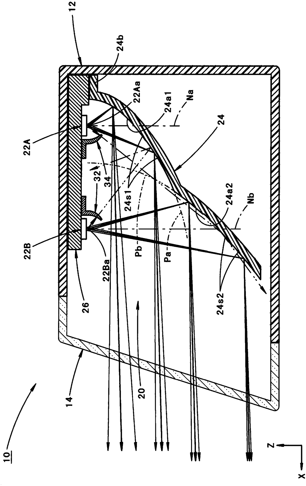
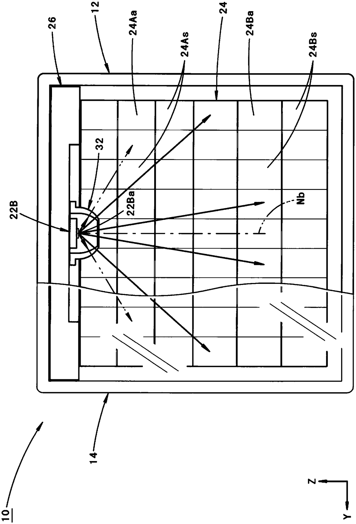
[0074] figure 1 is a side sectional view showing a vehicle lamp 10 according to an embodiment of the present invention, figure 2 is its front view.

[0075] As shown in these figures, the vehicle lamp 10 according to the present embodiment has a structure in which a lamp body 12 and a transparent light-transmitting cover 14 attached to the front end opening of the lamp body 12 are formed. Indoors, a lighting unit 20 is assembled.

[0076] Also, in these figures, the direction indicated by X is the "front" as the lamp (also "the front" as the vehicle), the direction indicated by Y is the "right direction", and the direction indicated by Z is the "upward direction" .

[0077] The lamp unit 20 is configured as follows: a first light emitting element 22A; a second light emitting element 22B disposed on the front side of the first light emitting element 22A; 2. Light emitted from ...


PUM


Abstract

The present invention provides a vehicle lamp which is configured such that light is reflected by a reflector so as to form a low-beam light distribution pattern and can improve forward visibility when a vehicle travels on a curved path curved toward an oncoming vehicle lane side. The reflector is configured to include a first reflecting surface which reflects light emitted from a first light emitting element to form a first light distribution pattern configuring a main portion of the low-beam light distribution pattern, and a second reflecting surface which reflects light emitted from a second light emitting element which is arranged at the lamp front side of the first light emitting element to form a second light distribution pattern for enhancing brightness of a lower vicinity region ofa cut-off line on an oncoming vehicle lane side. That is, the second reflecting surface is arranged in a surface normal direction of a light emitting surface of the second light emitting element on afront side of the first reflecting surface, so that the second light distribution pattern can be formed as a bright light distribution pattern which is bright and has a small vertical width.

Description

technical field [0001] The present invention relates to a vehicle lamp configured to reflect light emitted from a light source toward the front of the lamp by a reflector, thereby forming a light distribution pattern for low beam. Background technique [0002] Conventionally, as a vehicle lamp, a configuration is known in which emitted light from a light source is reflected toward the front of the lamp by a reflector, thereby forming a light distribution pattern for low beam. [0003] "Patent Document 1" describes a structure in which, in the vehicle lamp as described above, as its light source, there are a first light emitting element and a second light emitting element arranged on the front side of the lamp of the first light emitting element. element. [0004] The vehicle lighting device described in this "Patent Document 1" has a structure in which a light distribution pattern consisting of a part of the light distribution pattern for low beam is formed by turning on th...

Claims


Application Information

Patent Timeline
IPC IPC(8): F21S41/141F21S41/16F21S41/36F21S41/40F21Y113/20F21Y115/10F21Y115/30
CPCF21S41/16F21S41/36F21S41/141F21S41/40F21Y2115/30F21Y2113/20F21Y2115/10F21S41/336F21S41/43F21W2102/13F21S41/148F21W2102/19F21S41/663F21S41/321F21S41/19F21S41/147F21S41/285
Inventor 山本逸平
Owner KOITO MFG CO LTD
Why Eureka
Try Eureka