Vehicle Lamps

A technology for lamps and vehicles, applied in the direction of headlights, vehicle parts, lighting and heating equipment, etc., can solve the problem of not fully improving the maximum brightness and so on

Active Publication Date: 2020-03-27
KOITO MFG CO LTD
View PDF11 Cites 0 Cited by
  • Summary
  • Abstract
  • Description
  • Claims
  • Application Information

AI Technical Summary

Problems solved by technology

[0006] However, both of the left and right pair of light distribution patterns are formed by the irradiation light from the lamp unit using light-emitting diodes as the light source. Therefore, even if the two are partially overlapped, the maximum brightness cannot be sufficiently improved. There is room for improvement in front visibility

Method used


Image

  • Vehicle Lamps
  • Vehicle Lamps
  • Vehicle Lamps

Examples


Embodiment Construction

[0064] Hereinafter, embodiments of the present invention will be described with reference to the drawings. In the following embodiments, although various restrictions are made on the constituent elements, types, combinations, shapes, relative arrangements, etc., these are merely examples and the present invention does not Limited to this.

[0065] First, the first embodiment of the present invention will be explained.

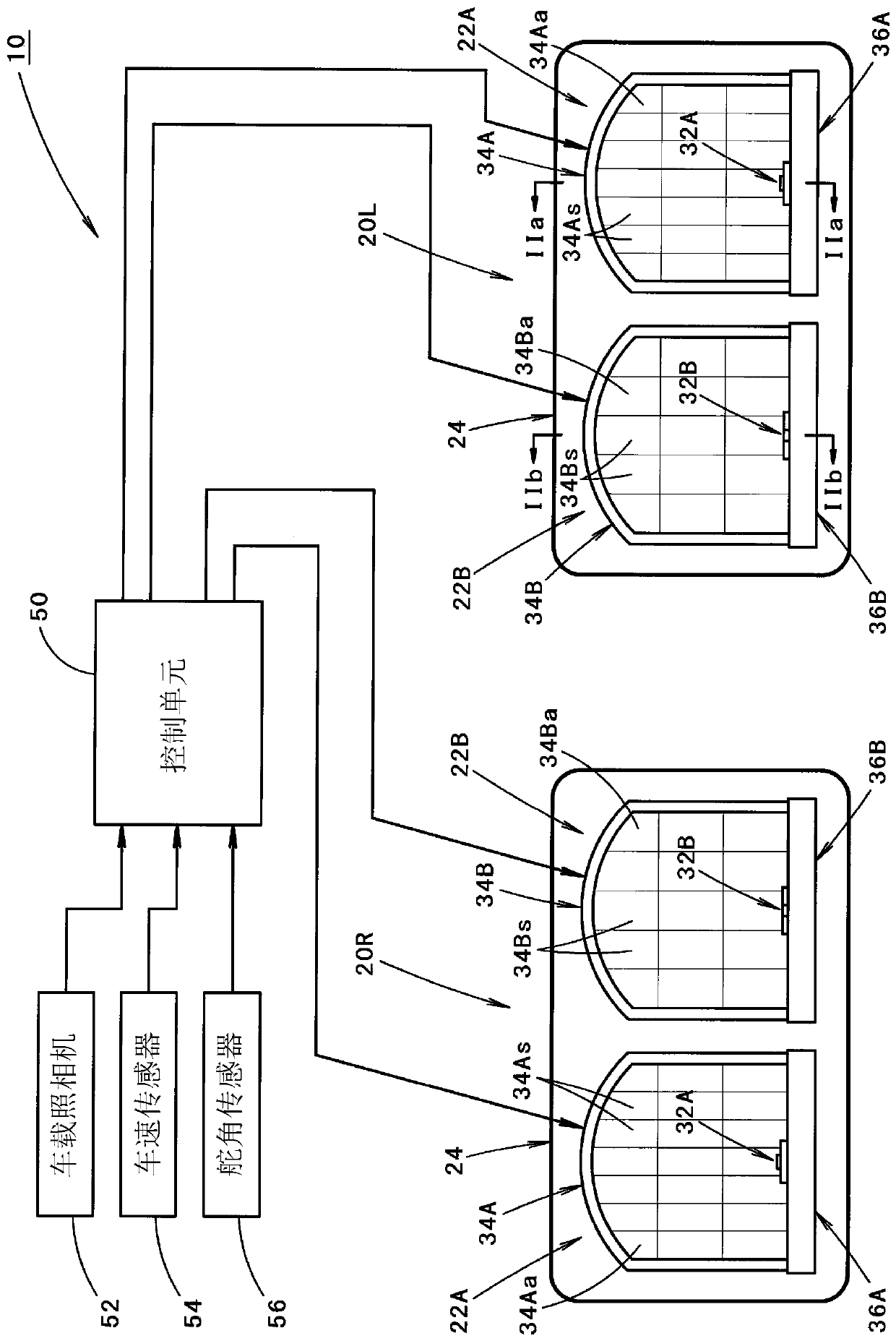
[0066] figure 1 It is a front view showing the vehicle lamp 10 according to the first embodiment of the present invention.

[0067] As shown in the figure, the vehicle lamp 10 is configured to include a pair of left and right lamp assemblies 20L, 20R, a control unit 50, an on-board camera 52 for taking pictures of the scene in front of the vehicle, a vehicle speed sensor 54, and a rudder angle sensor 56.

[0068] The pair of left and right lamp units 20L, 20R are lamp units arranged on the left and right sides of the front end of the vehicle, and have a bilaterally sy...


PUM


Abstract

The present invention relates to lamps for vehicles. The object is to improve the front visibility of the driver of the own vehicle in a vehicle lamp configured to form a pair of left and right light distribution patterns by irradiation light from a pair of lamp units. Each lamp assembly is composed of a first lamp unit using a light emitting diode as a light source and a second lamp unit using a laser diode as a light source, and a first light distribution pattern (PL1, PR1) is formed by the irradiated light from each first lamp unit. The irradiated light of each second lamp unit forms a second light distribution pattern (PL2, PR2) smaller and brighter than the first light distribution pattern (PL1, PR1). The pair of first light distribution patterns are formed at a required interval in the left and right direction, so that the pair of second light distribution patterns (PL2, PR2) are formed between the pair of first light distribution patterns (PL1, PR1) They are formed in a state of partially overlapping with each other and partially overlapping with a pair of first light distribution patterns ( PL1 , PR1 ).

Description

Technical field [0001] The present invention relates to a vehicle lamp configured to form a pair of left and right light distribution patterns by irradiated light from a pair of lamp units. Background technique [0002] Conventionally, as the structure of a vehicle lamp, a vehicle lamp in which a pair of left and right light distribution patterns are formed by irradiated light from a pair of lamp assemblies is known. [0003] "Patent Document 1" describes, as such a vehicle lamp, a vehicle lamp configured such that each lamp unit can be rotated in the left-right direction. [0004] [Patent Document 1] JP 2010-140661 A [0005] By using the vehicle lamp described in the aforementioned "Patent Document 1", a pair of left and right light distribution patterns can be formed integrally or separately. And, as a result, no glare is given to the driver of the oncoming car or the driver of the car driving ahead, and the front visibility of the driver of the own car can be ensured. [0006] How...

Claims


Application Information

Patent Timeline
Patent Type & Authority Patents(China)
IPC IPC(8): F21S41/141F21S41/16F21S41/657F21V7/00F21V14/02F21W102/20F21Y115/10
CPCB60Q1/12B60Q1/143B60Q2300/056B60Q2300/112B60Q2300/122B60Q2300/322B60Q2300/41B60Q2300/42F21S41/148F21S41/16F21S41/18F21S41/321F21S41/663F21S41/675F21W2102/14F21Y2115/10F21Y2115/30F21W2102/00B60Q1/1423B60Q1/16F21S41/147F21S41/32F21S41/60F21S41/62
Inventor 望月光之
Owner KOITO MFG CO LTD
Why Eureka
Try Eureka