

Controllable surface light source based on equal optical path
A technology of equal optical path and surface light source, applied in the field of light source, can solve the problems of shortening the service life of the light source, tight arrangement of lamp beads, poor overall effect, etc., achieving good irradiation effect, improving light efficiency and avoiding a lot of loss. Effect
- Summary
- Abstract
- Description
- Claims
- Application Information
AI Technical Summary
Problems solved by technology
Method used
Image

Examples
Embodiment 1
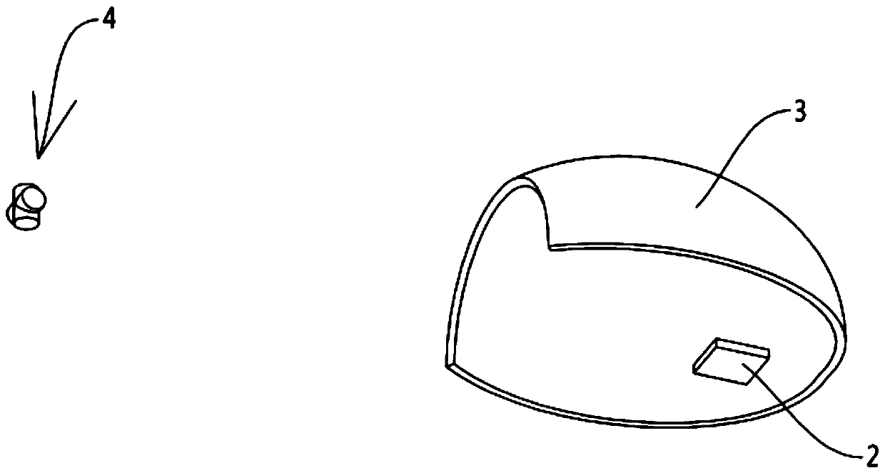
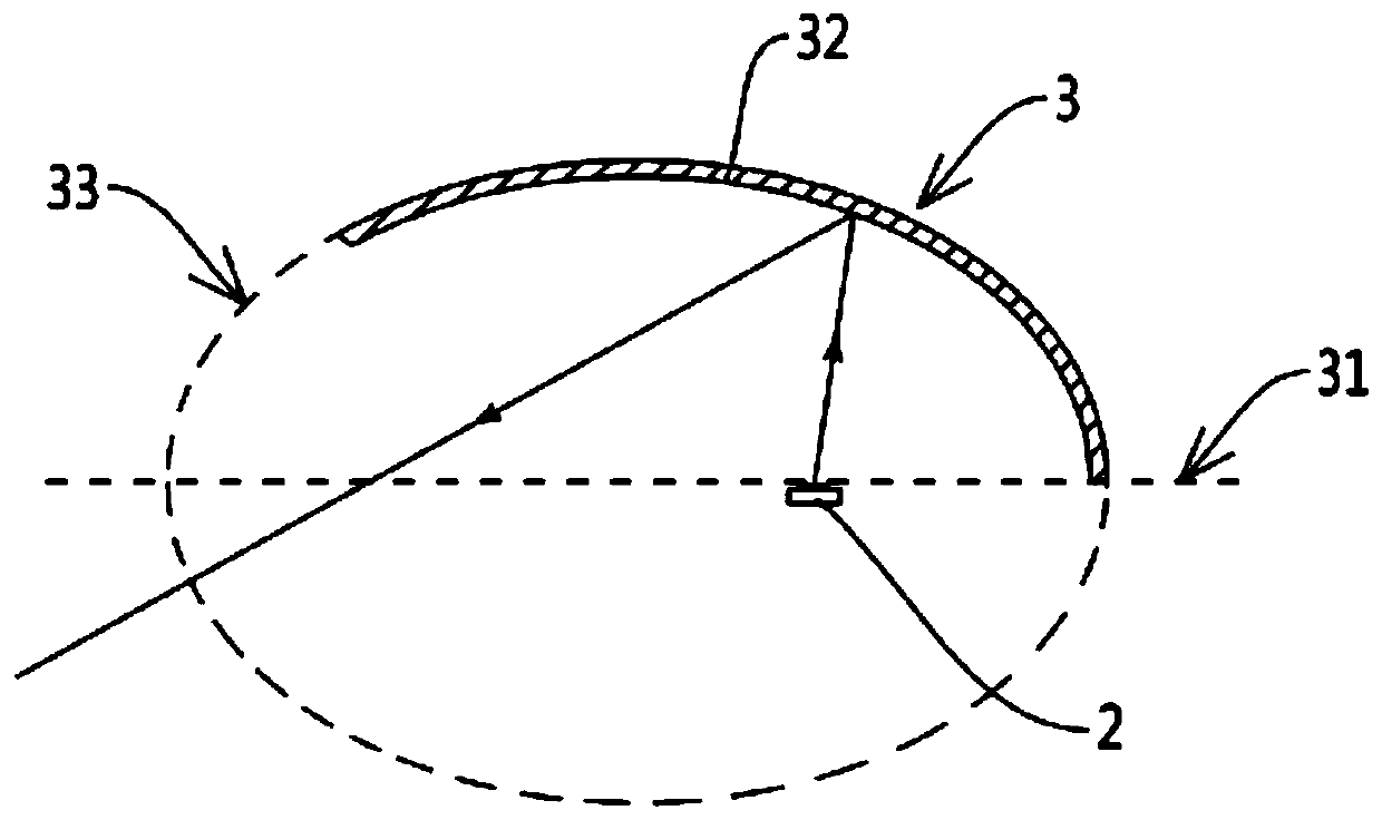
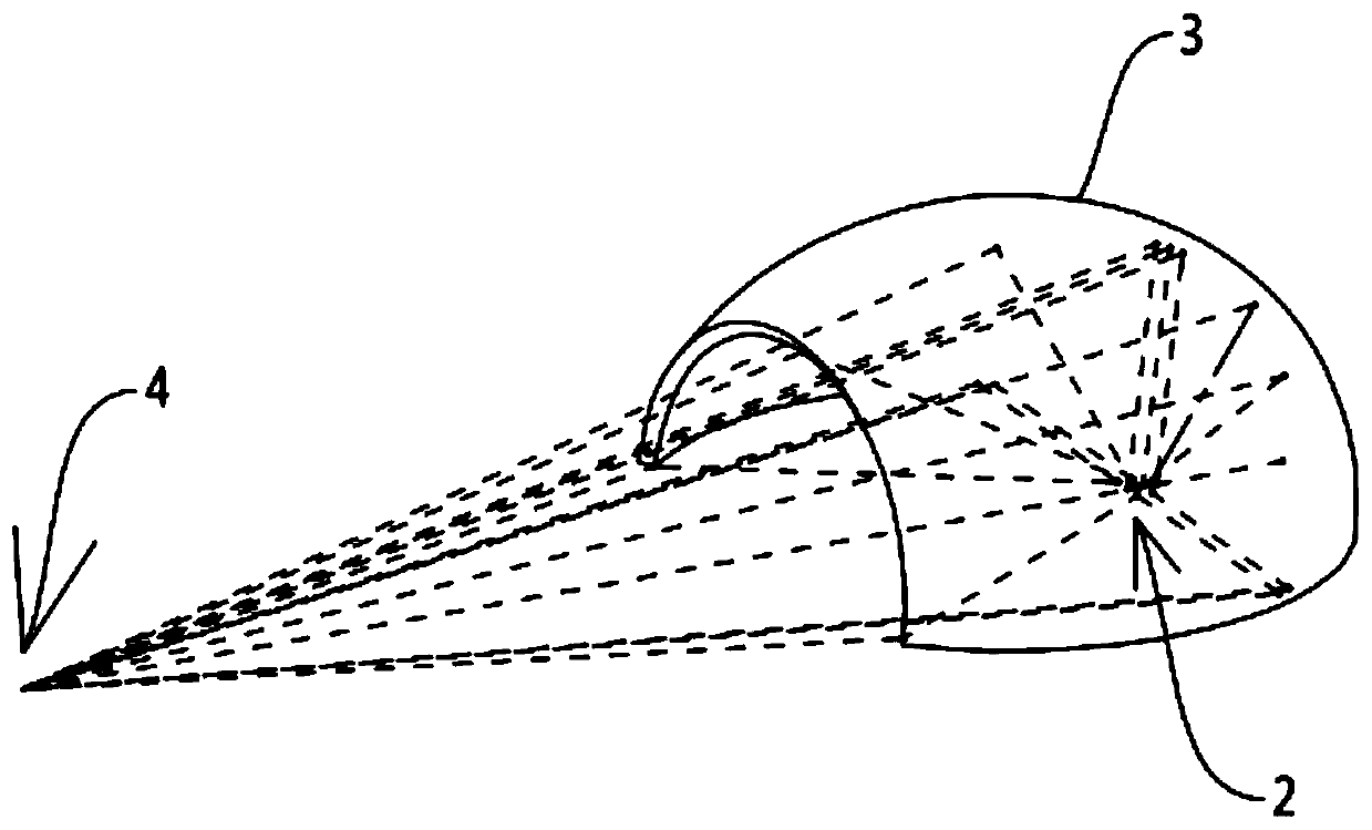
[0030] See Figure 1 to 5 , Figure 7 As shown, the controllable surface light source based on the equal optical path involved in this embodiment includes a lens 1 and a number of light source units located behind the lens 1; each light source unit includes a luminous body 2 and a reflective luminous body 2 The reflector 3 that emits light, the reflector 3 has a virtual rotation axis 31, any structure plane passing through the virtual rotation axis 31 cuts the reflector 3, and the intersection line 32 of the reflector 3 can emit the luminous body 2 in the structure plane Light and other optical path reflections, the intersection line 32 is intercepted by its structural ellipse 33, and the luminous body 2 is arranged on the virtual rotation axis 31 and coincides with the focal point of each structural ellipse 33.
[0031] Further, the light source units respectively form virtual light-emitting points 4 located between the lens 1 and the light source unit. The virtual light-emitting...
Embodiment 2
[0036] See Figure 1 to 4 , Image 6 , Picture 8 As shown, the controllable surface light source based on the equal optical path involved in this embodiment includes a lens 1 and a number of light source units located behind the lens 1; each light source unit includes a luminous body 2 and a reflective luminous body 2 The reflector 3 that emits light, the reflector 3 has a virtual rotation axis 31, any structure plane passing through the virtual rotation axis 31 cuts the reflector 3, and the intersection line 32 of the reflector 3 can emit the luminous body 2 in the structure plane Light and other optical path reflections, the intersection line 32 is intercepted by its structural ellipse 33, and the luminous body 2 is arranged on the virtual rotation axis 31 and coincides with the focal point of each structural ellipse 33.
[0037] Further, the light source units respectively form virtual light-emitting points 4 located between the lens 1 and the light source unit, and the virtu...
PUM
 Abstract
Description
Claims
Application Information