
Vehicle lamp

a technology for lamps and lampshades, applied in the field of lamps for lamps, can solve the problems of reducing regular reflectivity and reducing regular reflectivity, and achieve the effects of preventing yellow discoloration of the silver deposited reflecting surface, high regular reflectivity, and improving appearan

Inactive Publication Date: 2008-10-21
KOITO MFG CO LTD
View PDF7 Cites 0 Cited by
  • Summary
  • Abstract
  • Description
  • Claims
  • Application Information

AI Technical Summary

Benefits of technology

[0013]In addition, one or more embodiments of the present invention provide a vehicle lamp including a reflecting member with a silver deposited reflecting surface which can maintain a high regular reflectivity that cannot be obtained by the aluminum deposited reflecting surface over a long period of time.
[0037]In particular, in the event that the invention is applied to a headlamp, since the whole of the periphery of the aluminum deposited reflecting surface of the reflector is allowed to be seen exhibiting the calm pale silver-tinted color of the silver deposited surface of the extension reflector, thereby making it possible for the headlamp to which the invention is applied to be differentiated from the conventional headlamp having a glittering image in which the whole of the lamp body shines brightly owing to the aluminum deposited reflecting surfaces of the reflector and the extension reflector.

Problems solved by technology

However, the silver deposited coat reacts (generates silver oxide and silver sulfide) when contacting water, oxygen (heated oxygen) and sulfur dioxide gas (sweat, exhaust emissions) in the atmosphere to thereby be easily discolored (yellowed) and corroded, leading to a remarkable reduction in regular reflectivity.
In the reflector of JP-A-2000-106017 which utilizes the gas barrier properties of the top coat layer and the under coat layer which are made of the modified silicone resin, however, while the top coat layer and the under coat layer are effective to a certain extent in suppressing the discoloration (yellow discoloration) of the silver deposited reflecting surface (the silver deposited coat), there was caused a problem that discoloration and corrosion occur after many hours have elapsed (a heat resistance test of 400 hours), thereby reducing the regular reflectivity.

Method used


Image

  • Vehicle lamp
  • Vehicle lamp
  • Vehicle lamp

Examples


Embodiment Construction

[0051]Embodiments of the invention will be described with reference to the accompanying drawings.

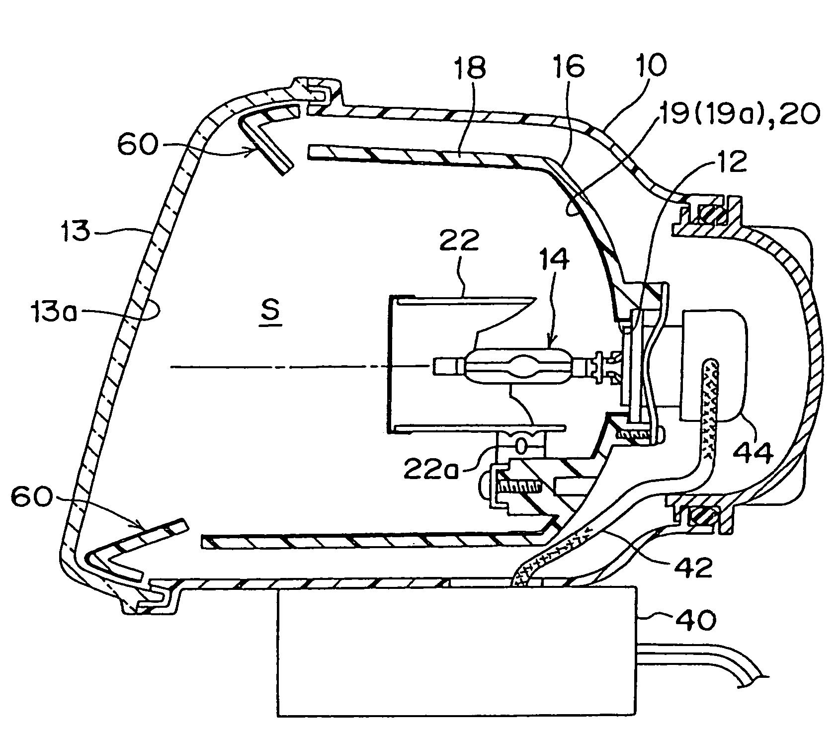
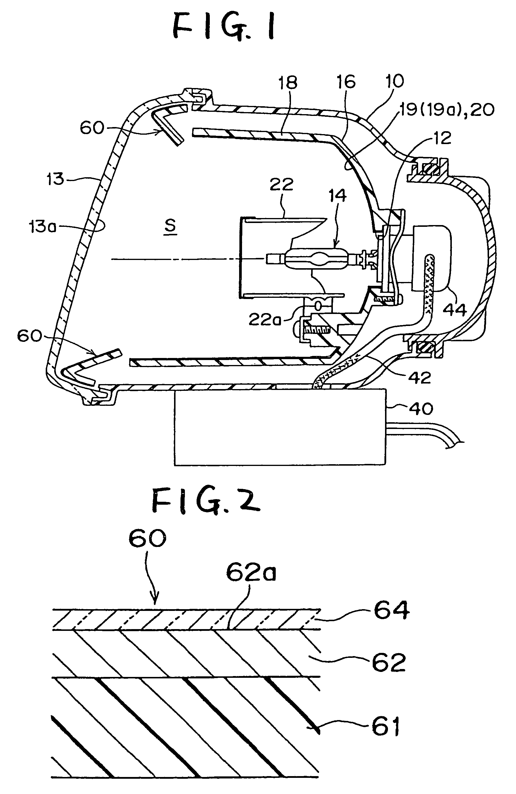
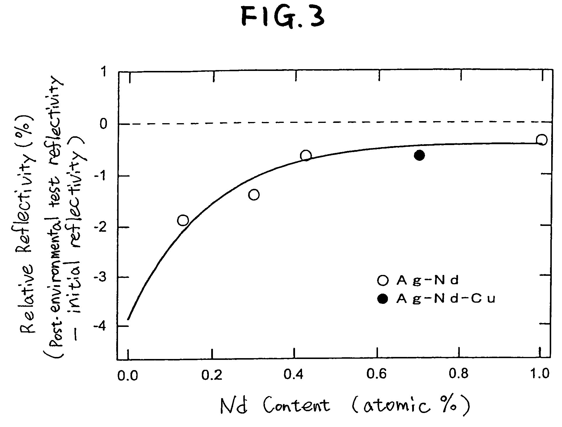
[0052]FIGS. 1 to 7 are drawings showing an embodiment of the invention. FIG. 1 is a vertical sectional view of an automotive headlamp according to an embodiment of the invention. FIG. 2 is an enlarged sectional view of a reflecting surface of an extension reflector provided in the headlamp of FIG. 1. FIG. 3 is a drawing showing a correlation between an amount of Nd added into an Ag / Nd alloy and the reflectivity of a silver alloy deposited reflecting surface. FIG. 4 is a drawing showing characteristics of elements added into the silver alloy. FIG. 5 is a drawing showing thermal conductivity, reflectivity, heat resistance and resistance to NaCl of Ag / Bi alloy, Ag / Nd / Cu alloy and pure Ag. FIG. 6A is a drawing explaining a function in which an Nd atom in a sliver deposited coat suppresses the agglomeration of Ag atoms (crystalline particles of Ag). FIG. 6B is a drawing explaining a function ...


PUM

PropertyMeasurementUnit
glass transition temperatureaaaaaaaaaa
reflectivityaaaaaaaaaa

Abstract

A reflecting member of a vehicle lamp is provided with a top coat layer formed on a silver deposited coat formed on a surface of a synthetic resin base. The top coat layer is made of a transparent acrylic resin which is synthesized with a monomer whose glass transition temperature is 60° C. or higher. The top coat layer adheres to the silver deposited coat to suppress the agglomeration of Ag atoms constituting the silver deposited coat.

Description

[0001]The present application claims foreign priority based on Japanese Patent Application No. P.2004-272344, filed on Sep. 17, 2004, the contents of which are incorporated herein by reference.BACKGROUND OF THE INVENTION[0002]1. Field of the Invention[0003]The present invention relates to a vehicle lamp having a reflecting member in a lamp compartment.[0004]2. Related Art[0005]As reflectors used for vehicle lamps such as headlamps which require high luminous intensity and extension reflectors which are disposed as decorative members in such a manner as to surround reflectors, there are known reflectors and extension reflectors in which a reflecting surface is made up of an aluminum deposited coat by applying an aluminum vapor deposition treatment to a surface of a synthetic resin base. In addition, since a high constant regular reflectivity of about 90% can be obtained on the aluminum deposited reflecting surface, such aluminum deposited reflecting surfaces are widely used not only ...

Claims


Application Information

Patent Timeline
Patent Type & Authority Patents(United States)
IPC IPC(8): F21V1/00F21V7/00B05D5/12B32B27/00F21W107/00
CPCF21S48/1394F21V7/22F21W2101/10F21S41/196F21S41/37F21S41/395F21S41/435F21S41/47F21W2102/135F21V7/24F21V7/28F21W2102/00
Inventor ONO, SHIGEKITAKIGUCHI, MASARUMURAKOSHI, MAMORUYAMAZAKI, KAZUHIROISHIGAKI, AKIO
Owner KOITO MFG CO LTD
Learn More