led flood light

A technology of LED floodlights and air vents, applied in the field of floodlights, can solve the problems of increased manufacturing cost, obstruction, and difficulty in obtaining heat dissipation effects, and achieve the effects of avoiding overheating, deterioration or damage

Active Publication Date: 2020-07-24
GLANZTECH
View PDF10 Cites 0 Cited by
  • Summary
  • Abstract
  • Description
  • Claims
  • Application Information

AI Technical Summary

Problems solved by technology

[0004] In some cases, heat sinks such as heat radiation fins are provided on the LED mounting board, but it is difficult to obtain sufficient heat dissipation effect only by this
It is also considered to install a forced cooling fan or a liquid circulation cooling structure, but the increase in manufacturing costs for this has become an obstacle to popularization

Method used


Image

  • led flood light
  • led flood light
  • led flood light

Examples


Embodiment 1

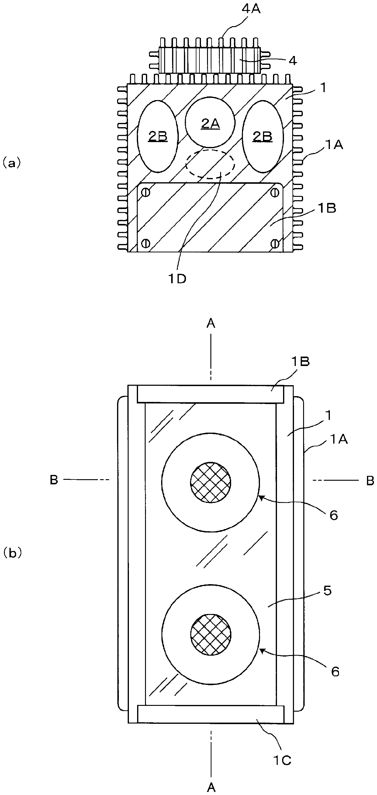
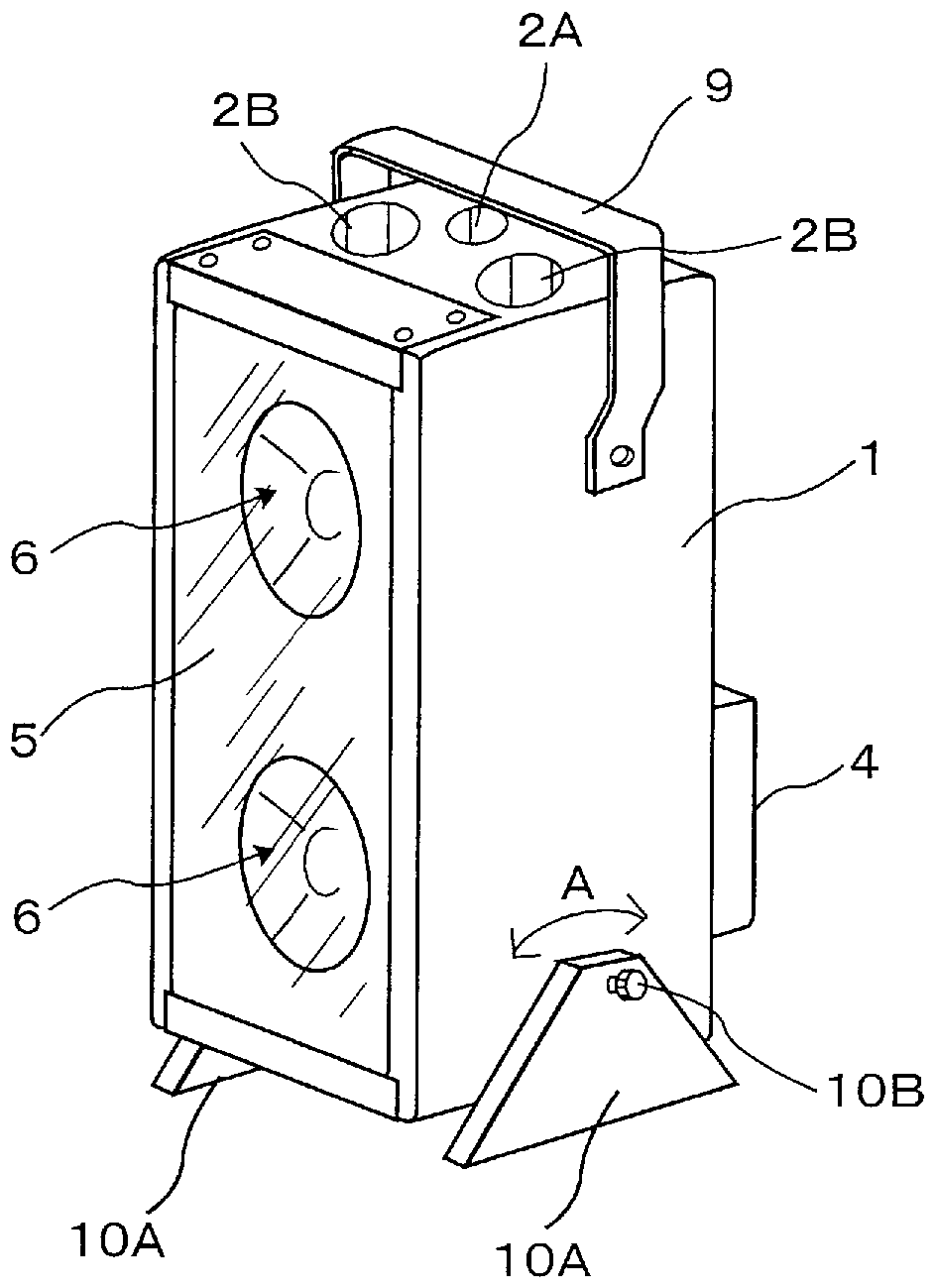
[0071] figure 1 Embodiment 1 of the LED floodlight of this invention is demonstrated, (a) is a top view, (b) is a front view. also, figure 2 right figure 1 Example 1 of the shown LED floodlight will be described, (a) is a right side view, and (b) is a bottom view. image 3 is along figure 1 (a) Cross-sectional view of line A-A. Such as figure 1 , figure 2 and image 3 As shown, regarding the LED floodlight of Example 1 of the present invention, an opening formed vertically by extruding a bulk material of aluminum as a metal material and having a groove 1E on one side is produced. The main body 1 of the groove 1E has a U-shaped cross-section perpendicular to the extrusion direction (longitudinal direction) of the extrusion molding. In the present embodiment, two LED units 6 are fitted in the longitudinal direction at the central portion viewed in the transverse section of the inner bottom wall 1F of the main body 1 formed as described above, in which the groove 1E is ...

Embodiment 2

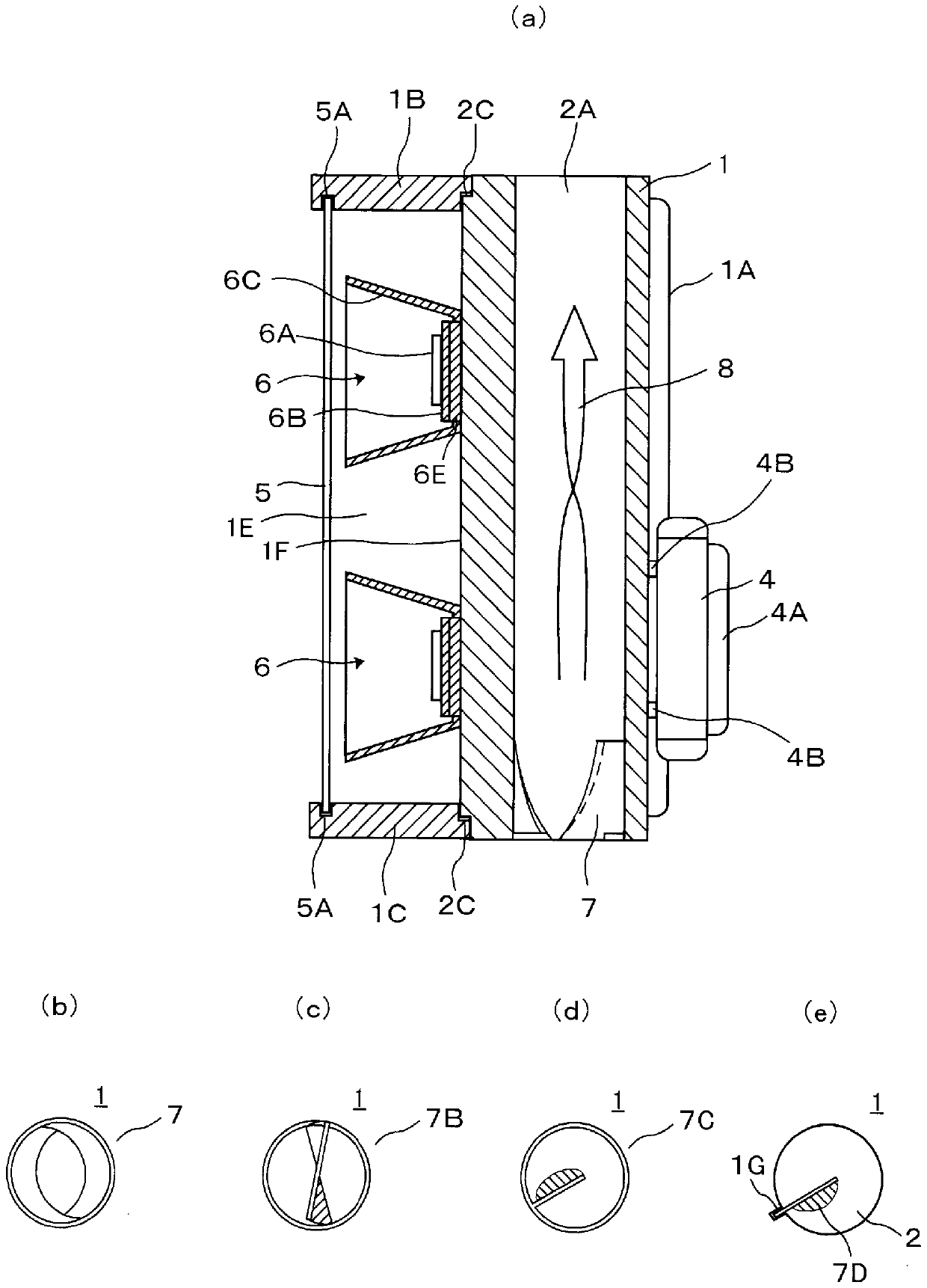
[0081] Figure 4 It is an explanatory diagram of Embodiment 2 of the LED floodlight of the present invention, (a) is the same as image 3 In the same sectional views, (b) to (e) are plan views of the vent hole viewed from the lower end or upper end of the vent hole for explaining various structural examples of the drift unit. In this embodiment, most of its structures and functions are the same as those described above with reference to Figure 1 to Figure 3 The described Example 1 is the same, so the description will focus on the parts different from Example 1. FIG. In Embodiment 1, the vent hole 2 provided on the main body 1 has a structure in which the air flowing in from the opening at the lower end rises directly along the inner wall of the vent hole 2 and is discharged to the external environment through the opening at the upper end.

[0082] In Example 2, a deflector means is provided inside the vent hole 2 to provide a swirling or turbulent flow to the air flow 8 ris...

Embodiment 3

[0087] Figure 5 It is the description of Embodiment 3 of the LED floodlight of the present invention along the line corresponding to figure 1 (b) Cross-sectional view of the cutting line of the B-B line. In this embodiment, the configuration is such that three ventilation holes with the same cross-sectional area are provided in the main body 1, and the region 1D having a large heat capacity is arranged on the back of the inner bottom wall 1F of the main body 6, and three ventilation holes are used. 2A, 2B, and 2C surround this region 1D having a large heat capacity. Furthermore, inner fins or flow deflecting units may also be provided inside the vent hole 2 .

[0088] Heat generated from the light emitting portion 6A of the LED unit 6 is transmitted to the main body 1 through the substrate 6B and the insulating base plate 6E similarly to the above-described respective embodiments. The transferred heat is first absorbed by the region 1D having a large heat capacity, suppres...


PUM


Abstract

To provide a light-weight LED floodlight that has a relatively simple structure and is easy to assemble without using a heat dissipation structure or a forced cooling unit of a complicated structure. It has: one or more LED units (6) assembled in the central part of the inner bottom wall (1F) of the main body (1) formed with the groove (1E), and the main body (1) is extruded by a metal material The opening of the groove (1E) is formed vertically and has a U-shaped cross section on one side. The main body (1) has one or more ventilation holes (2) formed by extrusion on the back side of the inner bottom wall (1F) of the groove (1E), parallel to the extrusion direction and open at the upper and lower ends. A region (1D) with large heat capacity is arranged between the inner bottom wall (1F) equipped with the LED unit (6) and the vent hole (2). The main body (1) has a chimney effect in which the LED unit (6) is turned on with the vertical direction of the vent hole (2) in the up-down direction, thereby transferring the heat conducted from the LED unit (6) to the The airflow rising in the air hole (2) is used for heat removal.

Description

technical field [0001] The present invention relates to a high-intensity floodlight in which a large number of LED chips are directly mounted on a substrate as a light-emitting unit, and more particularly to an LED floodlight having a structure for efficiently dissipating heat accompanying the lighting drive of the LED. lamp. Background technique [0002] Various lighting fixtures using LED elements (light-emitting diodes, hereinafter also simply referred to as LEDs) as light-emitting devices have been commercialized based on characteristics such as high luminance (high luminosity) and low power consumption. With regard to lighting fixtures using LEDs, they range from relatively low-intensity lighting fixtures for indoor lighting constructed by installing one or more LEDs in installation containers (light fixtures) to lighting fixtures used for night lighting at construction sites, public facilities or Large-scale floodlights for lighting stadiums and the like, and lighting...

Claims


Application Information

Patent Timeline
Patent Type & Authority Patents(China)
IPC IPC(8): F21S2/00F21V7/04F21V29/503F21V29/83F21Y115/10
CPCF21S8/08F21V3/02F21V15/013F21V15/015F21V21/30F21V31/005F21W2131/10F21S2/00F21V7/04F21V29/503F21V29/76F21V29/83F21Y2103/10F21Y2113/13F21Y2115/10F21K9/20F21V7/041F21V19/003F21V21/14F21Y2105/18
Inventor 庄司惠宣
Owner GLANZTECH
Why Eureka
Try Eureka