Novel hard alloy pipe fitting

A technology of cemented carbide and pipe fittings, which is applied in the direction of metal processing machinery parts, metal processing, metal processing equipment, etc., which can solve the problem of affecting the quality and speed of preparation of cemented carbide pipe fittings, affecting the production and processing efficiency of cemented carbide pipe fittings, and inconvenient adjustment of drill bits Rotation direction and other issues, achieve the effect of simple and convenient drilling steps, simple and convenient adjustment steps, and reduce manual operation steps

Inactive Publication Date: 2018-12-18
广州犀鸟工业设计有限公司
View PDF0 Cites 0 Cited by
  • Summary
  • Abstract
  • Description
  • Claims
  • Application Information

AI Technical Summary

Problems solved by technology

[0002] During the production and processing of cemented carbide pipe fittings, the punching of cemented carbide pipe fittings in the prior art mainly relies on manual adjustment and replacement of the drill bit, and the use efficiency is low. When the drill bit needs to be replaced repeatedly, it needs to be disassembled repeatedly, which greatly affects the cemented carbide pipe fittings. The preparation quality and preparation speed, and the traditional drilling equipment is not convenient to adjust the rotation direction of the drill bit. Therefore, the drilling has strong limitations and is inconvenient to use, which affects the production and processing efficiency of cemented carbide pipe fittings. It needs to be improved.

Method used


Image

  • Novel hard alloy pipe fitting
  • Novel hard alloy pipe fitting
  • Novel hard alloy pipe fitting

Examples


Embodiment Construction

[0014] Combine below Figure 1-3 The present invention will be described in detail.

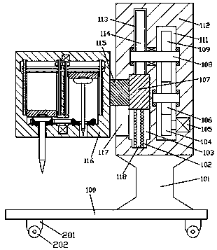
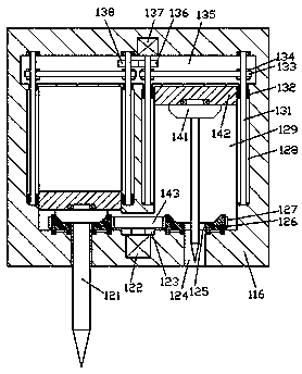
[0015] refer to Figure 1-3 , a new type of cemented carbide pipe fitting according to an embodiment of the present invention, comprising an underframe 100, a pole 101 is fixed on the top end surface of the underframe 100, and a mounting frame 112 is fixed on the top end surface of the pole 101, The left end of the installation frame 112 is provided with a processing frame 116, and the bottom end surface of the processing frame 116 is symmetrically provided with a first opening 124, and the inner top wall of the first opening 124 is provided with a control chamber 129 extending up and down. , the bottom wall of the control cavity 129 is rotated and installed with a conical frame 126, the outer periphery of the conical frame 126 is fixed with a toothed ring 127, and the upper and lower sides of the conical frame 126 are provided with the first through hole. 124 opposite to the second through...


PUM


Abstract

The invention discloses a novel hard alloy pipe fitting which comprises a bottom frame. A column rod is fixedly arranged on the top end face of the bottom frame. An installation frame is fixedly arranged on the top end face of the column rod. A machining frame is arranged at the left side end of the installation frame. First penetrating ports are bilaterally symmetrically formed in the bottom endface of the machining frame. Adjustment and control cavities extending up and down are formed in the inner top walls of the first penetrating holes. Conic frames are installed on the bottom walls of the adjustment and control cavities in a running fit mode. Toothed rings are fixedly arranged on the peripheries of the conic frames. Second penetrating ports opposite to the first penetrating ports are formed in the conic frames in an up-down run-through mode. Adjustment and control frames are installed in the adjustment and control cavities in a sliding fit mode. Conic wheels used for being engaged with the conic frames are installed at the bottom ends of the adjustment and control frames in a running fit mode. Drill bits are fixedly installed on the bottom end faces of the conic wheels and extend into the second penetrating ports and the first penetrating ports. A through hole is formed between the bottom ends of the adjustment and control cavities in the left side and the right side ina communicating mode.

Description

technical field [0001] The invention relates to the technical field of pipe fitting processing, in particular to a novel cemented carbide pipe fitting. Background technique [0002] During the production and processing of cemented carbide pipe fittings, the punching of cemented carbide pipe fittings in the prior art mainly relies on manual adjustment and replacement of the drill bit, and the use efficiency is low. When the drill bit needs to be replaced repeatedly, it needs to be disassembled repeatedly, which greatly affects the cemented carbide pipe fittings. The preparation quality and preparation speed, and the traditional drilling equipment is not convenient to adjust the rotation direction of the drill bit. Therefore, the drilling limitations are strong, the use is inconvenient, and the production and processing efficiency of the cemented carbide pipe fittings is affected, which needs to be improved. Contents of the invention [0003] The object of the present invent...

Claims


Application Information

Patent Timeline
Patent Type & Authority Applications(China)
IPC IPC(8): B23B39/16B23Q5/00B23Q5/04B23Q5/28
CPCB23Q5/28B23B39/16B23Q5/00B23Q5/04
Inventor 梁光勇
Owner 广州犀鸟工业设计有限公司
Why Eureka
Try Eureka