Automatic Parts Mounting Device
A part installation and parts technology, applied in the field of automatic parts installation devices, can solve the problems of too simple clamping tooling, low efficiency, parts damage, etc., and achieve the effect of simple and efficient sorting process and high efficiency
Inactive Publication Date: 2020-07-03
CHONGQING VOCATIONAL COLLEGE OF TRANSPORTATION
View PDF6 Cites 0 Cited by
- Summary
- Abstract
- Description
- Claims
- Application Information
AI Technical Summary
Problems solved by technology
The problem existing in the prior art is: the A part has two ends, one end has a plug, the other end does not have a plug, and the same B part also has an end with a slot and an end without a slot
[0005] 1. The clamping tooling is too simple. When installing the parts with plugs into the parts with slots, the installation accuracy is high. When the positioning accuracy of the parts is not high, it is easy to fail the installation or even damage the parts.
[0006] 2. The patent detects the direction of the parts one by one. If there is a mistake, then adjust the posture of the parts, and finally assemble the two parts. This method has too many intermediate links, too many steps that need to be stopped, and the assembly part needs to be started frequently Power components, the assembly process is not only inefficient, but also wears too much on the power components
Method used
View moreImage
Smart ImageViewing Examples

Examples
Embodiment Construction
[0025] Further detailed explanation through specific implementation mode below:
Login to View More PUM
 Abstract
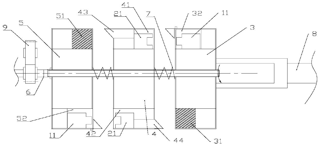
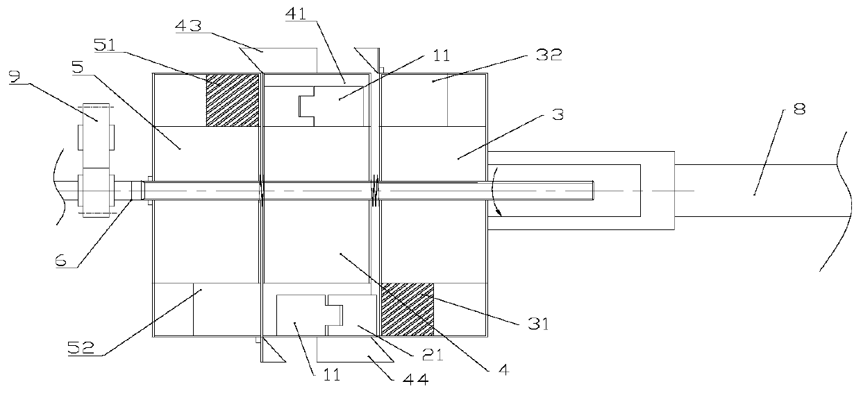
The invention relates to an assemble device of parts, in particular to an automate parts mounting device which comprises an array mechanism of a part A, an array mechanism of a part B and a mounting mechanism. The mounting mechanism comprises a forward mounting panel of the part A, a bi-directional mounting panel of the part B, the reverse mounting panel of the part A, a mounting shaft, two resetsprings, a horizontal driving part which drives the forward mounting panel to slide horizontally and a rotary driving part which drives a mounting shaft to rotate. The array mechanism of the part A isprovided with a forward material discharging channel and a reverse material discharging channel. The array mechanism of the part B is provided with the forward material discharging channel and the reverse material discharging channel. The mounting shaft is a spline shaft, the forward mounting panel, the reverse mounting panel and the bi-directional mounting panel are connected with the mounting shaft by spline shafts respectively. The mounting shaft is sleeved with reset springs. One reset spring is placed between the forward mounting panel and the bi-directional mounting panel, another resetspring is placed between the bi-directional mounting panel and the reverse mounting panel. The automate parts mounting device which is high efficient and can be completed to install quickly is provided.
Description
technical field [0001] The invention relates to a component assembly device, in particular to an automatic component installation device. Background technique [0002] At present, in the production process of auto parts, the installation and cooperation of two parts are involved. For example, part A has a plug, and part B has a slot. During the installation process, the plug of part A needs to be inserted into the slot of part B. The problem existing in the prior art is: A part has two ends, one end has a plug, the other end does not have a plug, and the same B part also has an end with a slot and an end without a slot. After the transfer, before the two parts are combined, it is found that the orientation of part A or part B is incorrect. It is necessary to adjust the orientation of the parts and then install the two parts together. This process was previously done manually, which is not efficient. [0003] The publication number is CN104889717B, and the name is an inventi...
Claims
Login to View More Application Information
Patent Timeline
 Patent Type & Authority Patents(China)
IPC IPC(8): B23P19/00B23P19/10
CPCB23P19/00B23P19/10
Inventor 罗宏
Owner CHONGQING VOCATIONAL COLLEGE OF TRANSPORTATION