Photovoltaic junction box

A technology for voltage junction boxes and cables, applied in the field of photovoltaic junction boxes, can solve the problems of inability to effectively fix positive and negative cables, easy displacement and deformation, etc.

Inactive Publication Date: 2018-12-18
意美旭智芯能源科技有限公司
View PDF7 Cites 0 Cited by
  • Summary
  • Abstract
  • Description
  • Claims
  • Application Information

AI Technical Summary

Problems solved by technology

[0005] The purpose of the present invention is to provide a photovoltaic junction box, which solves the defect that the existing photovoltaic connector cannot effectively fix the positive and negative cables, resulting in easy displacement and deformation

Method used


Image

  • Photovoltaic junction box
  • Photovoltaic junction box
  • Photovoltaic junction box

Examples


Embodiment 1

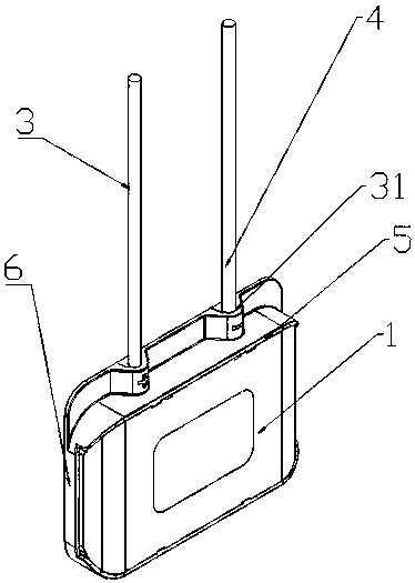
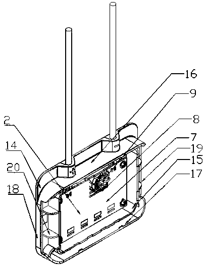
[0029] like figure 1 , figure 2 , image 3 , Figure 4 , Figure 5 As shown, a photovoltaic junction box provided by the present invention includes a box body 1, a power management module 2, a positive cable 3 and a negative cable 4, the box body includes an upper cover 5 and a bottom case 6; the positive The cable and the negative cable pass through the box to connect to the power management module; the power management module includes a PCB board 7, and the PCB board is provided with a mounting slot 8, and a low-frequency coil 9 is coupled to the mounting slot.

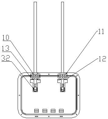
[0030] The positive cable and / or the negative cable is equipped with a limit block 10; the bottom case is provided with a first groove 11, and the bottom case is provided with a second groove 12 corresponding to the first groove, so The first groove and the second groove constitute a slot 13; wherein the limiting block is snapped into the slot. One end of the bottom case has a pair of through holes 31 respecti...

Embodiment 2

[0035] A photovoltaic junction box provided by the present invention includes a box body, a power management module, a positive cable and a negative cable, the box body includes an upper cover and a bottom case; the positive cable and the negative cable pass through the box The body is connected to the power management module;

[0036] The positive cable and / or the negative cable is equipped with a limit block; the upper cover is provided with a first groove, and the bottom shell is provided with a second groove corresponding to the first groove, and the first The groove and the second groove constitute a card slot; wherein the limiting block is locked into the card slot.


PUM


Abstract

The invention provides a photovoltaic junction box, comprising a box body, a power management module, a positive electrode cable and a negative electrode cable, wherein the box body comprises an uppercover body and a bottom shell; The positive electrode cable and the negative electrode cable pass through the box body and are connected with the power management module; A limit bit block is mountedon that positive electrode cable and/or the negative electrode cable; The bottom shell is provided with a first groove, the bottom shell is provided with a second groove corresponding to the first groove, and the first groove and the second groove form a clamping groove; Wherein the limiting block is clamped into the card slot. The invention solves the defect that the existing photovoltaic connector can not effectively fix the positive electrode cable and the negative electrode cable, which leads to easy displacement and deformation by fixing the limiting block on the positive electrode cableand the negative electrode cable, and fixing the limiting block through the upper cover body and the bottom shell.

Description

technical field [0001] The invention relates to the technical field of photovoltaic junction boxes, in particular to a photovoltaic junction box. Background technique [0002] In the existing photovoltaic junction box, the positive cable and the negative cable are directly inserted into the photovoltaic junction box, and the photovoltaic junction box is assembled together by directly snapping the upper and lower boxes, which cannot effectively fix the positive cable and the negative cable, resulting in easy displacement and deformation. [0003] For example, the patent application number is CN201620845867.1 "A Photovoltaic Junction Box with High Stability". The photovoltaic junction box is directly buckled by the upper and lower boxes, and the positive and negative cables are easy to shift and deform. Contents of the invention [0004] (1) Technical problems to be solved [0005] The object of the present invention is to provide a photovoltaic junction box, which solves ...

Claims


Application Information

Patent Timeline
Patent Type & Authority Applications(China)
IPC IPC(8): H02S40/34
CPCH02S40/34Y02E10/50
Inventor 袁震
Owner 意美旭智芯能源科技有限公司
Why Eureka
Try Eureka