
Method for transmitting and detecting control information, base station, user equipment and storage medium

A technology for controlling information and user equipment, which is applied in the directions of multiple use of transmission paths, transmission systems, digital transmission systems, etc. It can solve the problem of incompatibility of DCIformat transmission coverage performance, and achieve the effect of reducing the number of blind detections.

Inactive Publication Date: 2018-12-18
CHINA MOBILE COMM LTD RES INST +1
View PDF4 Cites 0 Cited by
  • Summary
  • Abstract
  • Description
  • Claims
  • Application Information

AI Technical Summary

Problems solved by technology

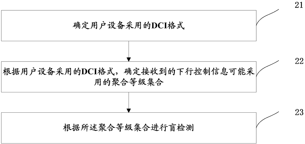
[0005] In view of this, the present invention provides a control information transmission and detection method, base station, user equipment, and storage medium, which are used to solve the problem that different DCI formats use the same aggregation level set, resulting in non-corresponding transmission coverage performance of different DCI formats

Method used


Image

  • Method for transmitting and detecting control information, base station, user equipment and storage medium
  • Method for transmitting and detecting control information, base station, user equipment and storage medium
  • Method for transmitting and detecting control information, base station, user equipment and storage medium

Examples


Embodiment 1

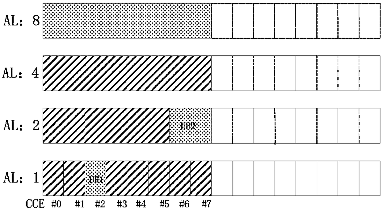
[0106] Suppose the number of bits in DCI format 1 is 20, the number of bits in DCI format2 is 60, the set of aggregation levels configured for DCI format1 is {1, 2, 4, 8}, and the set of aggregation levels configured for DCI format2 is {2, 4 , 8, 16}.

[0107] User equipment 1 to user equipment 4 transmit control information in a control resource set with a size of 20 MHz (110 PRB). The transmitted DCI formats are respectively DCI format1, DCI format1, DCI format2, and DCI format2, and the aggregation levels adopted by user equipment 1 to user equipment 4 are 1, 2, 8, and 16, respectively.

[0108] Please refer to image 3 and Figure 4 , image 3 It is a schematic diagram of user resource mapping on the aggregation level set of DCI format1 in Embodiment 1 of the present invention. Figure 4 It is a schematic diagram of user resource mapping on an aggregation level set of DCI format2 in Embodiment 1 of the present invention.

[0109] In the embodiment of the present inven...

Embodiment 2

[0111] The size of control channel resource set 1 is 20MHz (110PRB), and the size of control channel resource set 2 is 5MHz (25PBR). User equipment 1 and user equipment 2 transmit in control channel resource set 1 and control channel resource set 2 respectively.

[0112] The number of bits of DCI format 1 is 20, the number of bits of DCI format2 is 60, the set of aggregation levels configured for DCI format1 is {1, 2, 4, 8}, and the set of aggregation levels configured for DCI format2 is {2, 4, 8}. The DCI formats transmitted by the user equipment 1 and the user equipment 2 are respectively DCI format1 and DCI format2. In DCI format2, the aggregation levels adopted by user equipment 1 and user equipment 2 are 8 and 2 respectively.

[0113] Please refer to Figure 5 and Figure 6 , Figure 5 It is a schematic diagram of user resource mapping on the aggregation level set of DCI format1 in Embodiment 2 of the present invention. Figure 6 It is a schematic diagram of user re...


PUM


Abstract

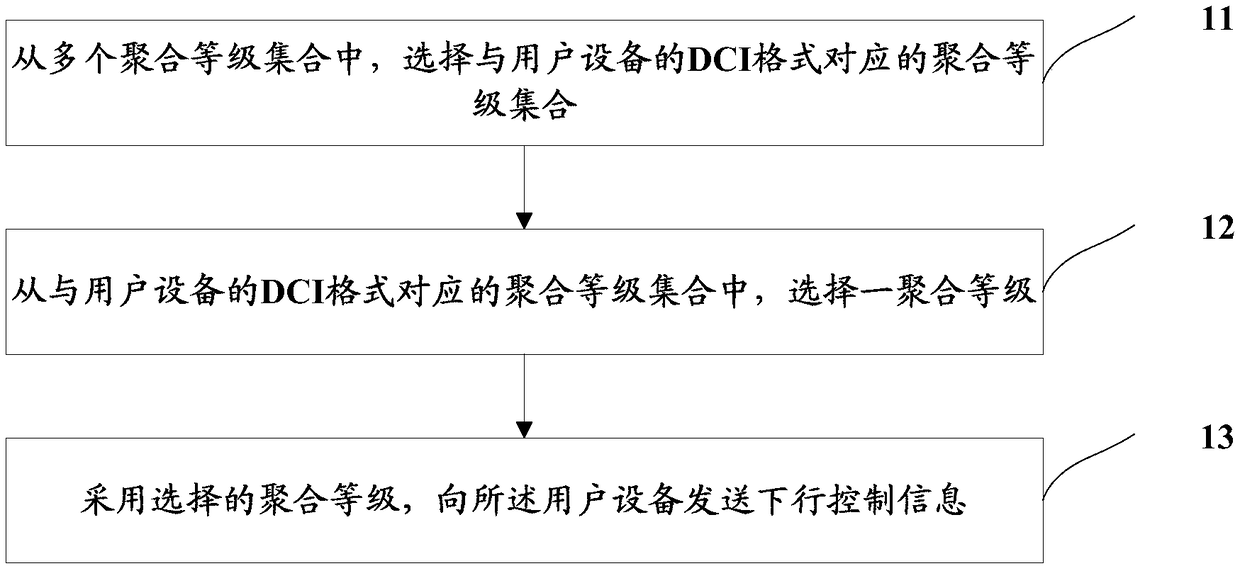
The invention provides a transmission and detection method of control information, a base station, a user equipment and a storage medium. The transmission method of the control information is used forthe base station. Selecting an aggregation level set from the aggregation level set corresponding to the DCI format of the user equipment; The downlink control information is transmitted to the userequipment using the selected aggregation level. In this invention, when the base station transmits the downlink control information to the user equipment, the aggregation level set corresponding to the DCI format of the user equipment is selected from multiple aggregation level sets. The method is different from the method that all DCI formats in the prior art adopt the same aggregation level set.The method of the invention can meet the coverage performance requirements of different DCI formats, and can reduce the blind detection times of the user equipment.

Description

technical field [0001] The present invention relates to the technical field of wireless communication, in particular to a control information transmission and detection method, a base station, user equipment and a storage medium. Background technique [0002] In the existing LTE system, a downlink control channel (PDCCH, Physical Downlink Control Channel) adopts different control signaling formats (DCI format, Downlink control information format) to transmit control information in different transmission modes (Transmission Mode). Different DCI formats (formats) transmit different signaling contents and bit numbers. In order to ensure the reliability of user equipment receiving the downlink control channel in different channel states, there are four different aggregation levels (AL, Aggregation Level) of 1 / 2 / 4 / 8 in the transmission of the existing downlink control channel, that is, a PDCCH contains 1 / 2 / 4 / 8 control channel elements (CCE, control channel element). The base st...

Claims


Application Information

Patent Timeline
IPC IPC(8): H04W72/04H04L5/00
CPCH04L5/0048H04W72/23
Inventor 孙奇倪吉庆韩双锋崔春风
Owner CHINA MOBILE COMM LTD RES INST
Learn More