Electric loader brake energy recovery transmission mechanism

A technology of energy recovery and transmission mechanism, applied in the direction of transmission, transmission parts, gear transmission, etc., can solve the problems of wasting electricity, braking energy cannot be recovered, frequent braking, etc., and achieve the effect of improving work efficiency

Inactive Publication Date: 2018-12-21
唐山鼎石汽车制造有限公司
View PDF0 Cites 0 Cited by
  • Summary
  • Abstract
  • Description
  • Claims
  • Application Information

AI Technical Summary

Problems solved by technology

[0002] During the working process of the electric loader, the brakes are the most frequent, and refueling after braking wastes a lot of electricity. The one-way overrunning clutch is used between the upper box and the lower box of the gearbox of the electric loader, and the braking energy cannot be recovered.

Method used


Image

  • Electric loader brake energy recovery transmission mechanism

Examples


Embodiment Construction

[0009] The present invention will be described in detail below in conjunction with the accompanying drawings and embodiments.

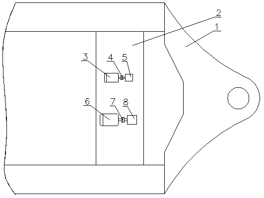
[0010] refer to figure 1 , a braking energy recovery transmission mechanism for an electric loader, consisting of an upper box 1, a first output shaft 2, a second output shaft 3, a first gear 4, a second gear 5, a double gear 6, an intermediate shaft 7, a key 8. The lower casing 9 and the planetary gear set 10 constitute.

[0011] The gearbox of the electric loader is composed of an upper box body 1 and a lower box body 9, the first output shaft 2 and the second output shaft 3 are installed in the upper box body 1, the first output shaft 2 is installed with the first gear 4, and the second output shaft The shaft 3 is fitted with a second gear 5 . A planetary gear set 10 is installed in the lower case 9 .

[0012] An intermediate shaft 7 is installed between the upper case 1 and the lower case 9, and one end of the intermediate shaft 7 is connected ...


PUM


Abstract

The invention relates to an electric loader, in particular to an electric loader brake energy recovery transmission mechanism. The electric loader brake energy recovery transmission mechanism comprises a gearbox upper box body and lower box body, a first output shaft and a second output shaft are mounted in the upper box body, the first output shaft is provided with a first gear, the second outputshaft is provided with a second gear, and a planetary gear set is mounted in the lower box body. An intermediate shaft is disposed between the upper box body and the lower box body, and one end of the intermediate shaft is connected to a sun wheel of the planetary gear set. The electric loader brake energy recovery transmission mechanism is characterized in that a duplicate gear is mounted on theother end of the intermediate shaft, the duplicate gear is connected with the intermediate shaft through a key, and the duplicate gear meshes with the first gear and the second gear separately. In the deceleration process of the electric loader, an accelerator pedal is retracted to form resistance to achieve brake and reverse charging effects, and the work efficiency is improved.

Description

technical field [0001] The invention relates to an electric loader, in particular to a braking energy recovery transmission mechanism of the electric loader. Background technique [0002] During the working process of the electric loader, the brakes are the most frequent, and refueling after braking wastes a lot of electricity. The one-way overrunning clutch is used between the upper box and the lower box of the gearbox of the electric loader, and the braking energy cannot be recovered. Contents of the invention [0003] The technical problem to be solved by the present invention is to provide a braking energy recovery transmission mechanism of the electric loader to charge the battery pack of the electric loader. [0004] A brake energy recovery transmission mechanism for an electric loader, comprising upper and lower boxes of a gearbox, a first output shaft and a second output shaft are installed in the upper box, the first output shaft is installed with a first gear, an...

Claims


Application Information

Patent Timeline
IPC IPC(8): F16H1/28F16H57/00
CPCF16H1/28F16H57/0025
Inventor 张坤王怀茂王立群
Owner 唐山鼎石汽车制造有限公司
Why Eureka
Try Eureka