Current limiter

A technology of current limiter and first flowing water, applied in the field of current limiter, can solve the problems of poor customer experience, poor current limiting effect, and unsmooth current limiting switching, and achieve guaranteed current limiting effect, good water outlet effect, The effect of increasing the water outlet area

Pending Publication Date: 2018-12-21
BEIJING KOHLER
View PDF0 Cites 1 Cited by
  • Summary
  • Abstract
  • Description
  • Claims
  • Application Information

AI Technical Summary

Problems solved by technology

[0003] Currently on the market current limiter, the current limiting effect is not good, and the current limiting switching is not smooth
Existing flow restrictors also restrict flow at low water pressure, resulting in poor customer experience at low water pressure

Method used


Image

  • Current limiter
  • Current limiter
  • Current limiter

Examples


Embodiment Construction

[0043] The specific implementation manner of the present invention will be further described below in conjunction with the accompanying drawings. Wherein the same components are denoted by the same reference numerals. It should be noted that the words "front", "rear", "left", "right", "upper" and "lower" used in the following description refer to the directions in the drawings, and the words "inner" and "outer ” refer to directions towards or away from the geometric center of a particular part, respectively.

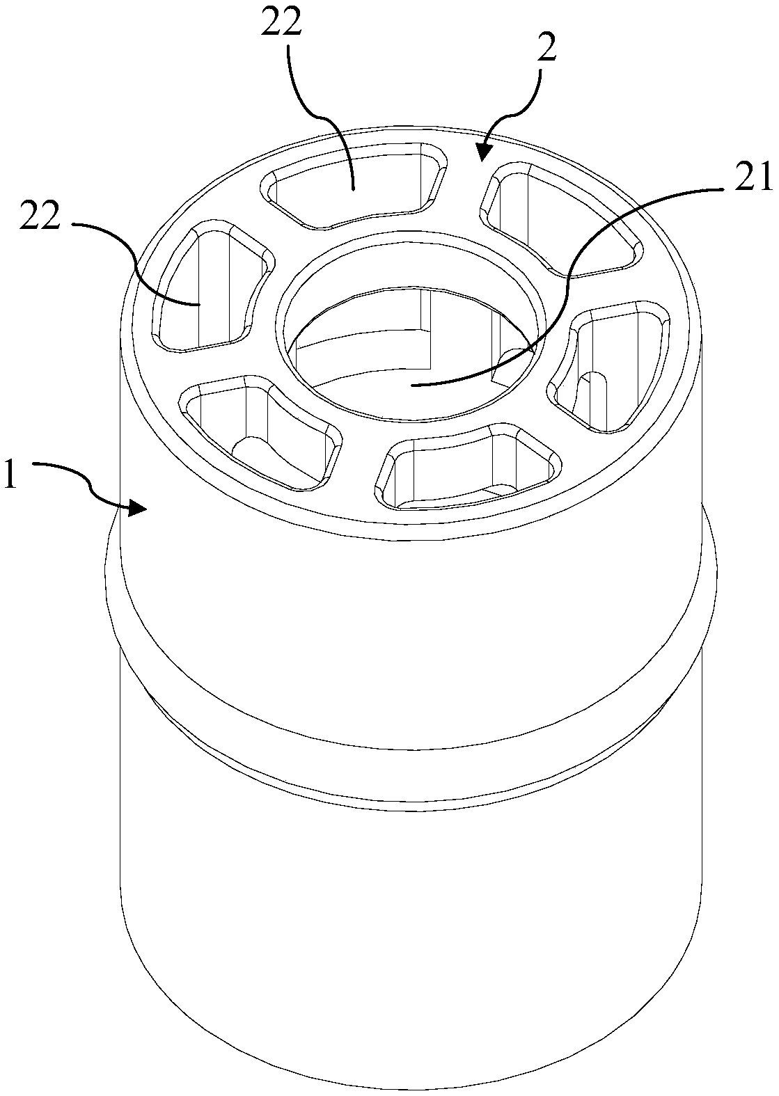
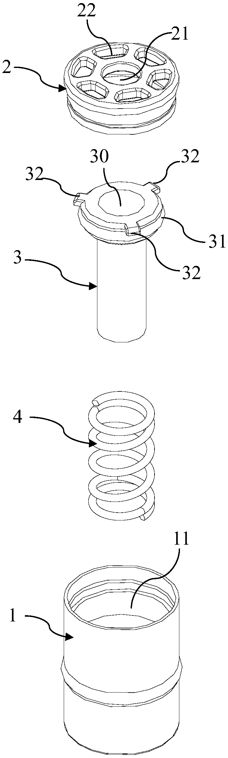
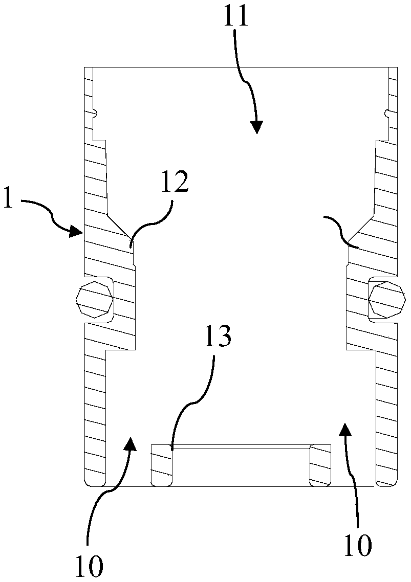
[0044] Such as Figure 1-6 As shown, the flow restrictor provided by an embodiment of the present invention includes a housing 1 with a mounting through hole 11 , an end cover 2 mounted on the housing 1 , and a slide rod 3 slidably mounted in the mounting through hole 11 .

[0045] There is a first water flow channel 30 in the slide bar 3 , and a second water flow channel 10 in the installation through hole 11 .

[0046] The end cover 2 has a first water inlet 21 comm...


PUM


Abstract

The invention discloses a current limiter which comprises a housing, an end cover and a sliding rod; a first flow channel is formed in the sliding rod, and a second flow channel is formed in a mounting through hole; the end cover is provided with a first water inlet and a second water inlet; the sliding rod has a first position and a second position in the mounting through hole. When the sliding rod is at the first position, the first flow channel and the second flow channel are in a conducting state respectively; and when the sliding rod is at the second position, the first flow channel is ina conducting state, and the second water flow channel is in a closed state. When the current limiter is in the low water pressure condition, the sliding rod is at the first position, and the first flow channel and the second flow channel are in the conducting state respectively, the water outlet area is increased, and the better water outlet effect is achieved; when the current limiter is in thehigh water pressure condition, the sliding rod is at the second position, the second flow channel is closed, and the current-limiting effect is ensured.

Description

technical field [0001] The invention relates to the technical field of bathroom plumbing, in particular to a flow limiter. Background technique [0002] In order to meet the flow requirements of the national standard, the existing bathroom products have added a flow restrictor device. [0003] The current limiter currently on the market has poor current limiting effect, and the current limiting switching is not smooth. Existing flow restrictors also restrict flow at low water pressure, resulting in a poor customer experience at low water pressure. Contents of the invention [0004] The purpose of the present invention is to provide a current limiter with simple structure and good current limiting effect. [0005] The technical solution of the present invention provides a flow restrictor, comprising a housing with a mounting through hole, an end cover mounted on the housing, and a slide bar slidably mounted in the mounting through hole; [0006] There is a first water fl...

Claims


Application Information

Patent Timeline
Patent Type & Authority Applications(China)
IPC IPC(8): F16K17/34G05D7/01
CPCF16K17/34G05D7/0133
Inventor 阳赛魏绍佩
Owner BEIJING KOHLER
Why Eureka
Try Eureka