
Stamping part conveying device for special steel casting

A technology for conveying devices and stamping parts, which is applied in the direction of conveyors, transportation and packaging, loading/unloading, etc. It can solve the problems of lack of protection for stamping parts, damage of stamping parts, low efficiency, etc., to save transportation time and prevent slipping , easy sliding effect

Pending Publication Date: 2018-12-25
江苏同生高品合金科技有限公司
View PDF3 Cites 0 Cited by
  • Summary
  • Abstract
  • Description
  • Claims
  • Application Information

AI Technical Summary

Problems solved by technology

[0004] The purpose of the present invention is to provide a conveying device for stamping parts for special steel casting, to solve the problem that when the conveying device proposed in the above-mentioned background technology is in use, when special steel is cast, the required conveying device should be able to improve its processing efficiency, The general conveying device does not have the function of protecting the stamping parts, which may cause damage to the stamping parts during the conveying process, and the conveying efficiency of the general conveying device is relatively low.

Method used


Image

  • Stamping part conveying device for special steel casting
  • Stamping part conveying device for special steel casting
  • Stamping part conveying device for special steel casting

Examples


Embodiment Construction

[0019] The following will clearly and completely describe the technical solutions in the embodiments of the present invention with reference to the accompanying drawings in the embodiments of the present invention. Obviously, the described embodiments are only some, not all, embodiments of the present invention. Based on the embodiments of the present invention, all other embodiments obtained by persons of ordinary skill in the art without making creative efforts belong to the protection scope of the present invention.

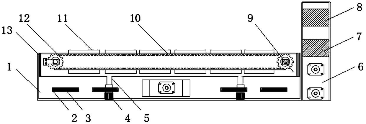
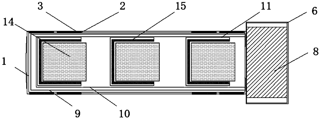
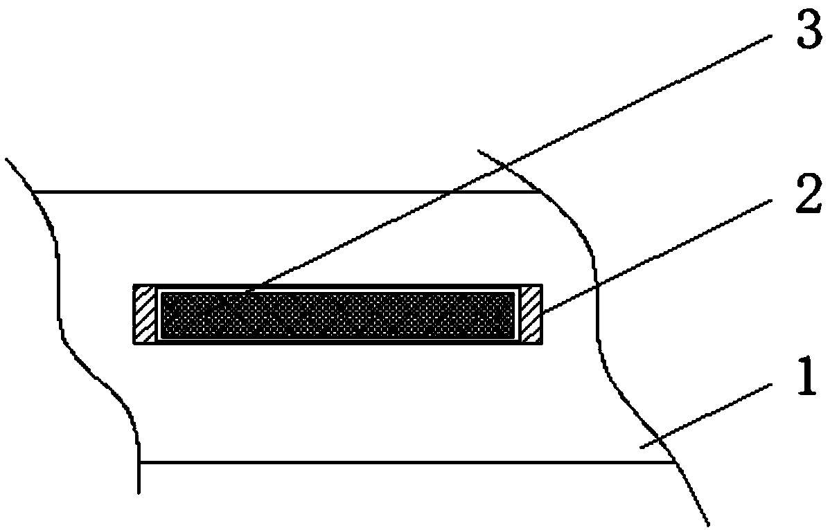
[0020] see Figure 1-3 , the present invention provides a technical solution: a conveying device for stamping parts for special steel casting, including a main seat 1, a chute block 2, a breathable net 3, a motor 4, a movable rod 5, a conveying seat 6, and a first conveying port 7 , the second delivery port 8, transmission seat 9, conveyor belt 10, side plate 11, gear 12, chute plate 13, friction layer 14 and pad layer 15, the outer walls of the left and right...


PUM


Abstract

The invention discloses a stamping part conveying device for special steel casting. The device comprises a main seat and a transmission seat; ventilation screens are arranged on the outer walls of theleft and right ends of the main seat; sliding chute blocks are mounted at the left and right ends of the ventilation screens; the sliding chute blocks are movably connected with the ventilation screens; the sliding chute blocks are welded with the main seat; a motor is fixed in the main seat; a movable rod is arranged at the upper end of the motor; the movable rod is fixedly connected with the motor; and a conveying seat is connected with the rear end of the main seat. According to the stamping part conveying device for special steel casting, a side plate and a cushion layer are arranged, theside plate is arranged on a conveyer belt, and the side plate is C-shaped, so that when stamping parts are conveyed by the conveyer belt, the side plate can block the stamping parts and prevent the stamping parts from sliding off; and the cushion layer is arranged on the inner wall, and the cushion layer is made of rubber and the like and has the characteristic of being soft, so that the stampingparts can be prevented from being damaged due to bump and a role in protection is played.

Description

technical field [0001] The invention relates to the technical field of conveying devices, in particular to a conveying device for stamping parts for special steel casting. Background technique [0002] The conveying device is a device for conveying some product objects. It is generally used in factories. When casting special steel, a conveying device is needed to convey its stamped parts. When conveying, efficiency is more important. , and should also ensure the integrity of stamping parts. [0003] When the conveying device on the market is in use, when casting special steel, the required conveying device should be able to improve its processing efficiency, while the general conveying device does not have the function of protecting stamping parts, which may cause damage during the conveying process. The stamping parts are damaged, and the conveying efficiency of the general conveying device is relatively low. Therefore, we propose a stamping part conveying device for speci...

Claims


Application Information

Patent Timeline
Patent Type & Authority Applications(China)
IPC IPC(8): B65G15/58B65G15/56B65G21/12B65G23/06B65G69/20
CPCB65G15/56B65G15/58B65G21/12B65G23/06B65G69/20
Inventor 贲东建
Owner 江苏同生高品合金科技有限公司
Learn More