
Guardrail with optimized structural on construction machinery

A technology for construction machinery and guardrails, which is applied to the field of guardrails with optimized structures on construction machinery, can solve the problems of narrow space, inconvenient passage or operation, and low safety, and achieve the effect of increasing the passage size.

Inactive Publication Date: 2018-12-25
东莞市金越信息科技有限公司
View PDF6 Cites 0 Cited by
  • Summary
  • Abstract
  • Description
  • Claims
  • Application Information

AI Technical Summary

Problems solved by technology

[0002] At present, construction machinery operation platforms or passages generally have guardrails. The guardrails play a role of safety protection for operators. Due to the large size of some construction machinery, considering the state of mobile transportation, the width of the platform passage is narrow. It is not easy to pass or operate. At present, most of them are disassembled to meet the space requirements. The operation is difficult and the safety is low.
The existing fixed guardrail has no possibility of increasing space, and the space is narrow, which affects the passage and maintenance of operators; while the detachable guardrail is inconvenient to operate and requires multiple people to assist in the operation, which is time-consuming and laborious

Method used


Image

  • Guardrail with optimized structural on construction machinery
  • Guardrail with optimized structural on construction machinery

Examples


Embodiment

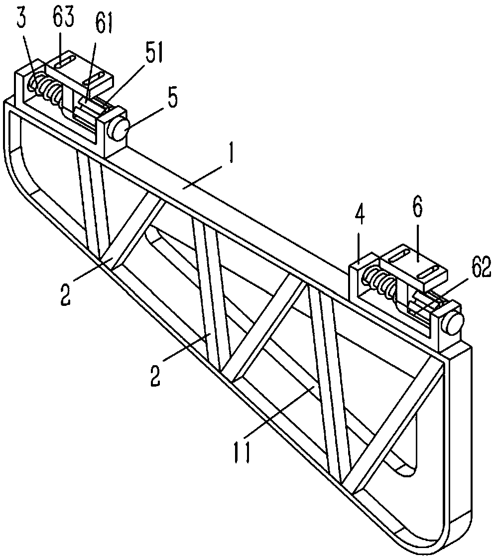
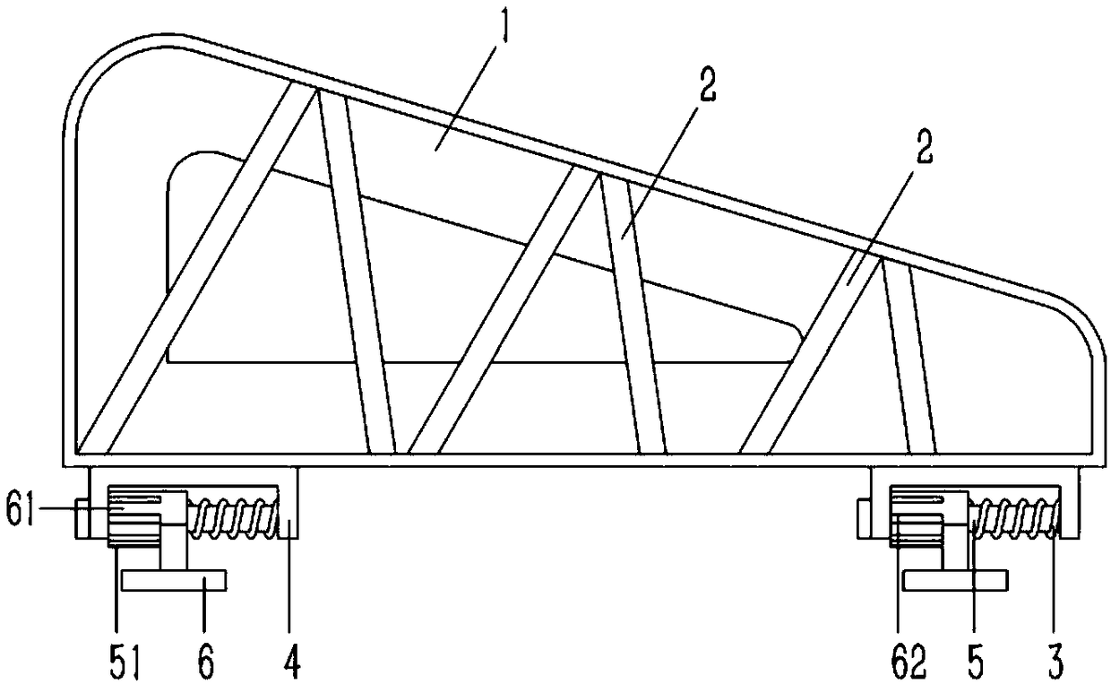
[0015] Example: see figure 1 , 2 As shown, a structure-optimized guardrail on construction machinery includes a guardrail 1, the periphery of the guardrail 1 is formed with flanging, and a number of inclined support railings 2 are fixed on the guardrail 1, and the two ends of the support railings 2 are fixed On the flanging, several flip positioning brackets are fixed on the flanging at the bottom of the slab 1, and the flip positioning bracket includes a connecting frame 4 in the shape of "冂", the connecting frame 4 is inserted and fixed with a rotating shaft 5, and the bottom of the connecting frame 4 The side is provided with a T-shaped fixed seat 6, the upper end of the fixed seat 6 is inserted on the rotating shaft 5, and one side of the upper end of the fixed seat 6 is formed with a shaft sleeve 61, and several roads are formed on the shaft sleeve 61 to penetrate the inner and outer walls of the shaft sleeve 61. Slot 62, a positioning plate 51 is formed on the outer wal...


PUM


Abstract

The invention discloses a guardrail with an optimized structure on construction machinery. The guardrail with the optimized structure on the construction machinery comprises a fence plate, wherein a flanging edge is shaped in the periphery of the fence plate, supporting railings are fixed on the fence plate, and the two ends of the supporting railings are fixed to the flanging edge. A plurality offlipping positioning brackets are fixed to the flanging edge of the bottom end of the fence plate, the flipping positioning brackets comprise n-shaped connecting frames, rotating shafts are fixed tothe connecting frames in a inserted mode, and T-shaped fixed seats are arranged on the lower side of the connecting frames. The upper ends of the fixed seats are inserted on the rotating shafts in a sleeving mode, shaft sleeves are arranged on the one side of the upper end of each fixed seat in a forming mode, a plurality of inserting grooves penetrating through the inner and outer walls of the shaft sleeves are formed in the shaft sleeves in a forming mode, the outer walls of the rotating shafts are arranged on positioning plates in a forming mode, and the positioning plates are arranged intothe inserting grooves of the shaft sleeves in a inserting mode. The upper ends of the fixed seats, away from the shaft sleeves, are pressed against compression springs, the compression springs are inserted on the rotating shafts in a sleeving mode, and the other ends of the compression springs are pressed against the connecting frames. The guardrail with the optimized structure on the construction machinery can increase the effective passing size without reducing the safety of people, meet the passage space required by most operators, and avoid the waste of manpower and material resources caused by the dismantling of the guardrail.

Description

Technical field: [0001] The invention relates to the technical field of engineering machinery, and more specifically relates to a structure-optimized guardrail on the engineering machinery. Background technique: [0002] At present, construction machinery operation platforms or passages generally have guardrails. The guardrails play a role of safety protection for operators. Due to the large size of some construction machinery, considering the state of mobile transportation, the width of the platform passage is narrow. It is not easy to pass or operate. At present, most of them are disassembled to meet the space requirements. The operation is difficult and the safety is low. The existing fixed guardrail has no possibility of increasing space, and the space is narrow, which affects the passage and maintenance of operators; while the detachable guardrail is inconvenient to operate and requires multiple people to assist in the operation, which is time-consuming and laborious. ...

Claims


Application Information

Patent Timeline
Patent Type & Authority Applications(China)
IPC IPC(8): F16P1/02
CPCF16P1/02
Inventor 徐亚维
Owner 东莞市金越信息科技有限公司
Learn More