Structurally integrated in-situ actuation fully-displaced composite amplified piezoelectric inchworm linear platform

A compound amplification and electric inchworm technology, which is applied to piezoelectric effect/electrostrictive or magnetostrictive motors, electrical components, generators/motors, etc., can solve the problems of reduced platform life, low platform movement speed, and motion stability Reduce and other problems, achieve the effect of reducing the processing and assembly precision requirements, compact platform structure, and improving stability

Active Publication Date: 2018-12-28
NINGBO UNIV
View PDF5 Cites 2 Cited by
  • Summary
  • Abstract
  • Description
  • Claims
  • Application Information

AI Technical Summary

Problems solved by technology

[0003] 1) Use the external clamping method (that is, the clamping mechanism is located outside the moving table) to clamp the moving table, the platform structure is not compact, and the moving table is small;
[0004] 2) The structure is split, that is, the clamping mechanism and the driving mechanism are designed and manufactured separately, and then they are assembled into one body. Not only the assembly and adjustment process is complicated, but also the contact stiffness between the clamping mechanism and the driving mechanism will be reduced , increase the damping, thereby reducing the natural frequency of the platform and deteriorating the dynamic response characteristics;
[0006] 4) The output displacement of the clamping unit is small, which will make the clamping unit unable to fully clamp or release the moving table, and the moving table cannot be fully clamped, the clamping force it receives will be small, and the motion stability will be reduced ; If the moving table cannot be fully released, serious friction and wear will occur, re

Method used


Image

  • Structurally integrated in-situ actuation fully-displaced composite amplified piezoelectric inchworm linear platform
  • Structurally integrated in-situ actuation fully-displaced composite amplified piezoelectric inchworm linear platform
  • Structurally integrated in-situ actuation fully-displaced composite amplified piezoelectric inchworm linear platform

Examples


Embodiment Construction

[0041] Embodiments of the present invention will be further described in detail below in conjunction with the accompanying drawings.

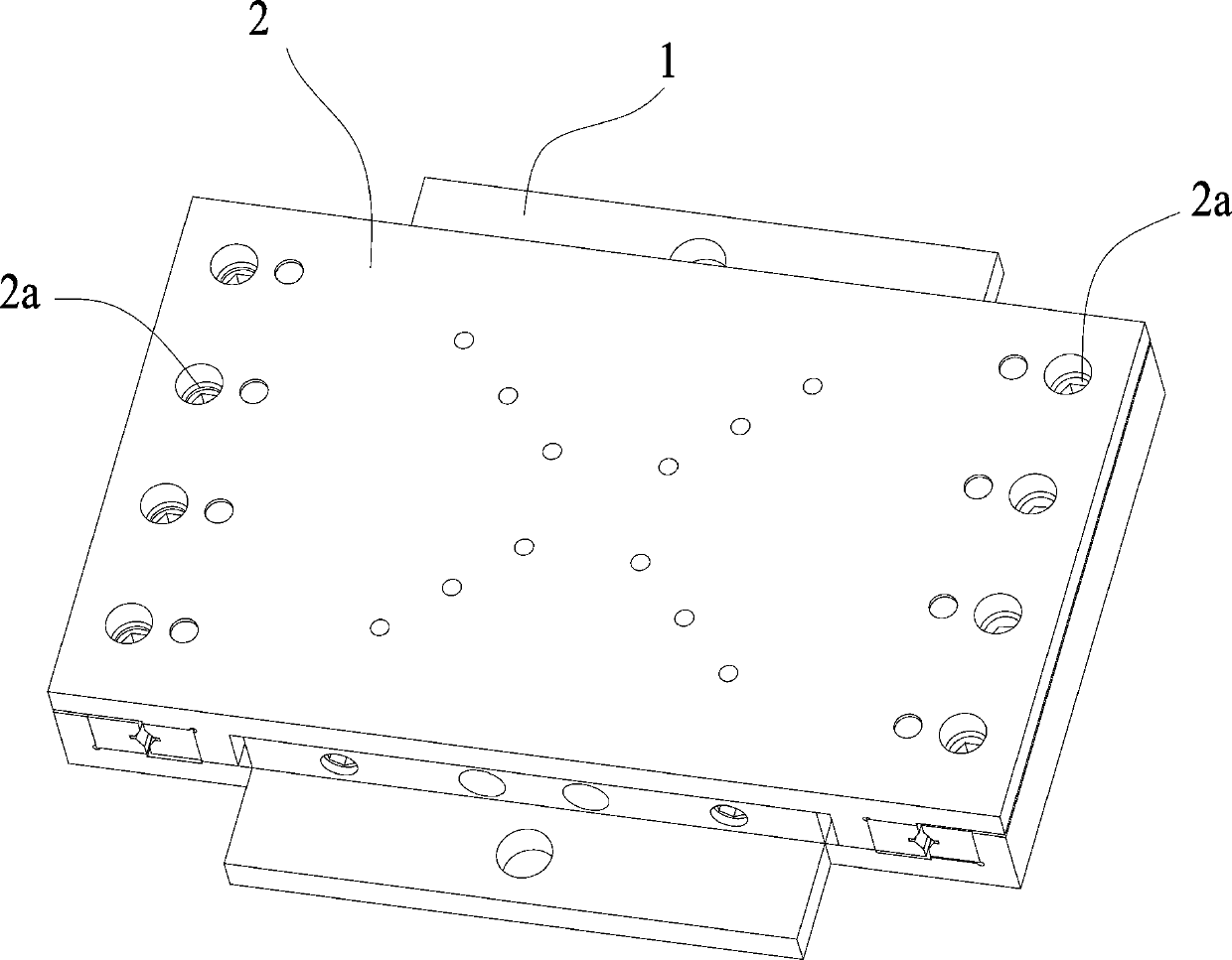
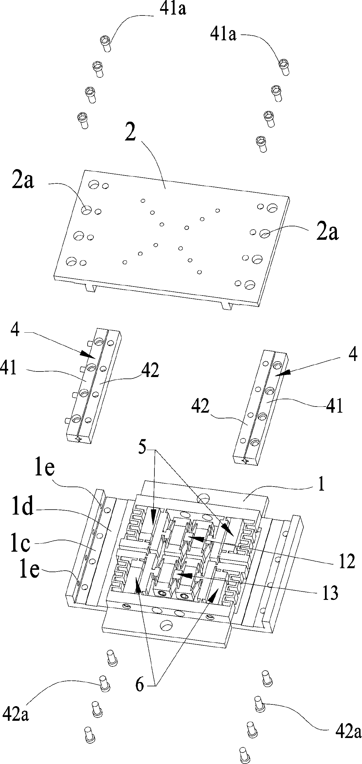
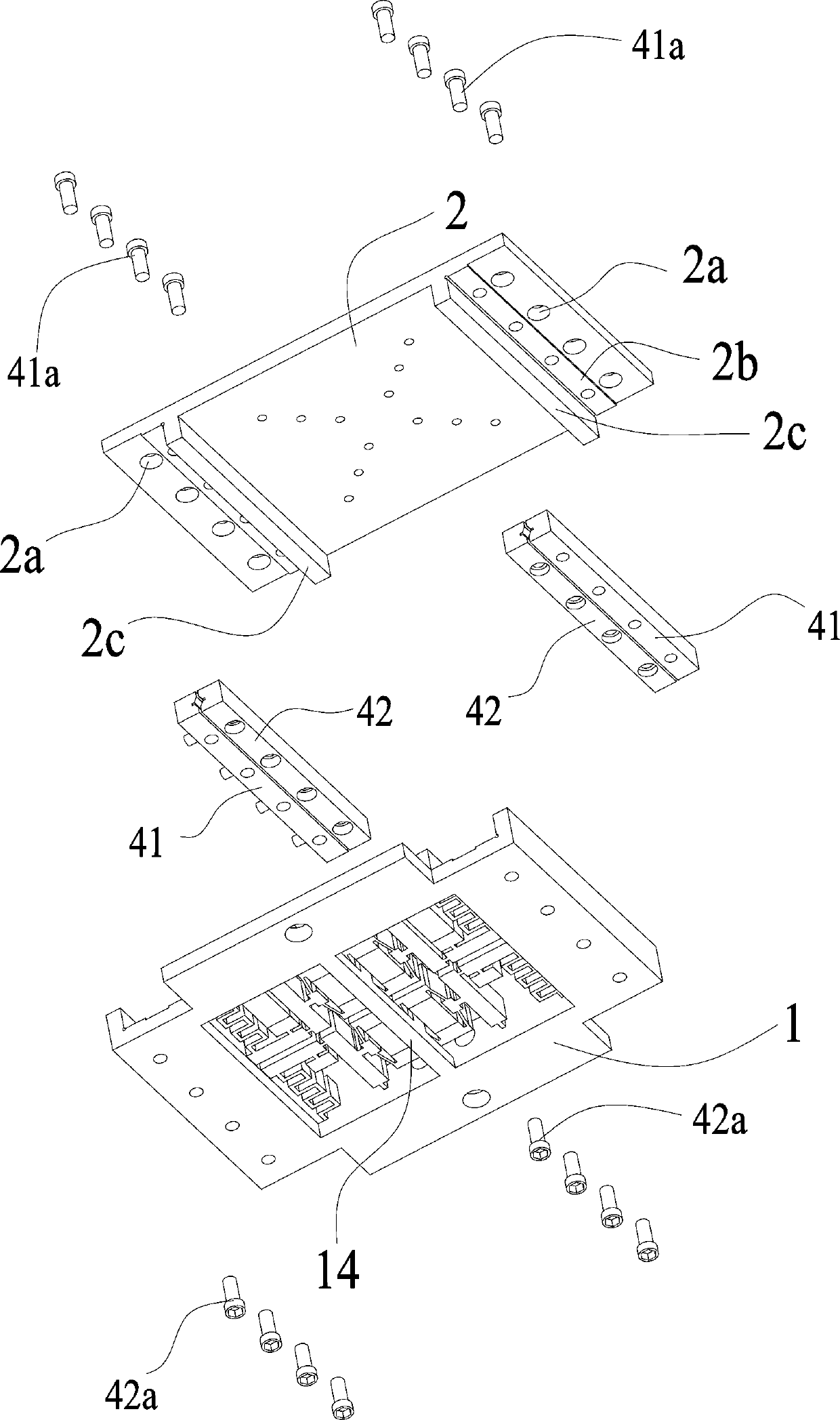
[0042] Figure 1 to Figure 7 It is a schematic diagram of the structure of the present invention, as shown in the figure, the structurally integrated in-situ drive full-displacement composite amplified piezoelectric inchworm linear platform of the present invention includes a fixed platform 1 and a moving table that is slidably connected by two cross roller guide rails 4 2. There are two retaining bars 2c parallel to the cross roller guide rail 4 under the moving table 2; the first clamping group 12 and the second clamping group 12 arranged along the length direction of the retaining bars 2c are arranged between the two retaining bars 2c. The clamping group 13, the first clamping group 12 and the second clamping group 13 perform telescopic movement along the direction perpendicular to the bar 2c, and their telescopic ends are respectively conne...


PUM


Abstract

A structurally integrated in-situ actuation fully-displaced composite amplified piezoelectric inchworm linear platform comprises a fixed platform and movable platform tops slidably connected through two cross roller guide rails, and stopper bars are arranged below the movable platform tops. A first clamping group and a second clamping group, and a first driving group and a second driving group arearranged between the two stopper bars, and driving units make telescopic movement along the length direction of the stopper bars; each driving unit comprises a clamping arm connected with the telescopic end of the driving unit, the clamping arms release and clamp the stopper bars, and a movable gap is arranged between the adjacent clamping arms. The first clamping group, the first driving group,the second clamping group and the second driving group are sequentially controlled to make the movable platform tops walk and position in an inchworm-like manner. The platform has the advantages of compact structure, large movable table tops, integrated clamping and driving mechanism, low requirement for the machining and assembling precision of the clamping and driving mechanism, sufficient clamping and releasing, power-off clamping, fast moving speed and small moving error.

Description

technical field [0001] The invention belongs to the field of nano-positioning technology, and relates to a nano-positioning platform with a large stroke and high resolution, in particular to a structure-integrated in-situ driven full-displacement composite amplified piezoelectric inchworm linear platform. Background technique [0002] Piezoelectric inchworm linear stage is a precision positioning platform with large stroke and high resolution. Based on the principle of inchworm crawling in bionics, it continuously accumulates the small displacement of the piezoelectric actuator to form a continuous large stroke displacement. Compared with the electromagnetic linear motor type platform, the piezoelectric inchworm linear platform has the advantages of small size, no heat generation, easy control, no end effect and thrust fluctuation; compared with ultrasonic resonance type, inertial drive type piezoelectric linear stage , has the advantages of large output force, high power d...

Claims


Application Information

Patent Timeline
IPC IPC(8): H02N2/02H02N2/04
Inventor 崔玉国张志豪娄军强杨依领惠相君周鹏飞
Owner NINGBO UNIV
Why Eureka
Try Eureka