Semi-automatic cleaning and soaking equipment

A semi-automatic, equipment-based technology, applied in cleaning methods and utensils, cleaning methods using liquids, chemical instruments and methods, etc., can solve problems such as inability to adjust the temperature of soaking liquid, low cleaning and soaking efficiency, and difficulty in adding soaking liquid, etc., to achieve perfection Soaking functions and conditions, improving operating efficiency and operating safety, and reducing the effect of direct labor intensity

Inactive Publication Date: 2019-01-04
JIANGSU TONGSHENG PHOTOELECTRIC TECH CO LTD
View PDF0 Cites 3 Cited by
  • Summary
  • Abstract
  • Description
  • Claims
  • Application Information

AI Technical Summary

Problems solved by technology

[0003] In view of the above situation, in order to overcome the defects of the prior art, the present invention provides a semi-automatic cleaning and soaking equipment, which effectively solves the difficulty of adding soaking liquid when the staff cleans and soaks the lens, the temperature of the soaking liquid cannot be adjusted and the cleaning and soaking efficiency is low, and the personnel work intense problem

Method used


Image

  • Semi-automatic cleaning and soaking equipment
  • Semi-automatic cleaning and soaking equipment
  • Semi-automatic cleaning and soaking equipment

Examples


Embodiment 1

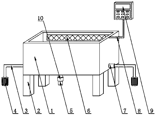
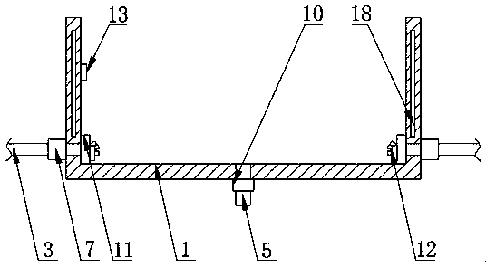
[0018] Embodiment one, by figure 1 , figure 2 with Figure 5 Given, the present invention includes a soaking box 1, the top side of the soaking box 1 is fixed with a control panel 9 through a bracket 8, which facilitates centralized control and effectively improves the convenience of use, and a temperature controller 22 is installed inside the control panel 9 , the center of the bottom of the soaking tank 1 is embedded with a sewage pipe 5, the first electromagnetic valve 10 is installed on the sewage pipe 5, the water injection main pipe 11 is fixed on both sides of the bottom of the soaking tank 1 by bolts, and several water injection main pipes 11 are installed. A high-pressure nozzle 12, the center of one side of the water injection main pipe 11 is connected with the water outlet of the high-pressure water pump 4 by the water inlet pipe 3, and the junction of the water inlet pipe 3 and the soaking tank 1 is equipped with a second electromagnetic valve 7, and one part of ...

Embodiment 2

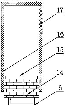
[0019] Embodiment two, on the basis of embodiment one, by figure 1 with image 3 Out, the sewage discharge mechanism 6 comprises a cover 14, a dirt storage tank 15, a second filter screen 16 and a first filter screen 17, the dirt storage tank 15 is fixed on the top side of the soaking tank 1 by bolts, and the soaking tank 1 is connected with the dirt storage tank. The top joint of the tank 15 is embedded with a first filter screen 17, the bottom of the other side of the dirt storage tank 15 is embedded with a second filter screen 16, and the bottom of the dirt storage tank 15 is clamped and fixed with a cover 14. The tumbling of the liquid, the dirt after soaking and cleaning floats, flows into the inside of the dirt storage tank 15 through the first filter screen 17, and makes the soaking liquid flow out after being filtered through the second filter screen 16, so that the dirt remains in the dirt storage tank The inside of 15 is cleaned and dirty by disassembling the cover ...

Embodiment 3

[0020] Embodiment 3, on the basis of Embodiment 2, a seal ring is bonded and fixed around the cover 14, and the seal ring is a rubber material member, which can effectively prevent the soaking liquid from leaking from the cover 14 and the dirt storage tank 15. The overflow at the connection effectively improves the convenience of use.


PUM


Abstract

Disclosed is semi-automatic cleaning and soaking equipment. The problems that when a worker cleans and soaks a lens, soaking solution is difficult to add, the temperature of the soaking solution cannot be adjusted, cleaning and soaking efficiency is low, and work intensity of the worker is high are solved. The semi-automatic cleaning and soaking equipment comprises a soaking box. A control panel is fixed to one side of the top of the soaking box through a support. A temperature controller is installed in the control panel. A dirt discharge pipe is installed in the bottom center of the soakingbox in an embedded mode. A first electromagnetic valve is installed on the dirt discharge pipe. Water injection main pipes are fixed to the bottom two sides of the soaking box through bolts and are provided with a plurality of high-pressure nozzles. The centers of one sides of the water injection main pipes are connected with water outlets of a high-pressure water pump through water inlet pipes. The semi-automatic cleaning and soaking equipment is novel in structure, ingenious in design and convenient to use, the soaking function and conditions are perfected to a great extent, the solution settemperature can be adjusted, meanwhile the soaking effect is also improved greatly, direct labor intensity of people is lowered, and work efficiency and operation safety are improved.

Description

technical field [0001] The invention relates to the technical field of lens production, in particular to a semi-automatic cleaning and soaking equipment. Background technique [0002] During the lens production process, there will be a lot of dirt on the surface of the lens, as well as the protective paint used to protect the lens grinding surface. It is impossible to carry out lens quality inspection and post-processing. The lens can only be cleaned with an ultrasonic cleaning machine, but At present, the washing machine cleaning has certain limitations. Some lenses cannot be cleaned at one time. It is necessary to add a soaking tank for pretreatment. The soaking tank currently used is too simple. The disadvantages are: 1. There is no water pipe and drain pipe, and there is only one stainless steel tank. , You need to add water with a scoop, and lift the trough to pour water. 2. Without heating function, it cannot meet the requirements of various temperature lens immersion...

Claims


Application Information

Patent Timeline
Patent Type & Authority Applications(China)
IPC IPC(8): B08B3/10B08B3/08B08B13/00
CPCB08B3/10B08B3/08B08B13/00
Inventor 何同军汪渊
Owner JIANGSU TONGSHENG PHOTOELECTRIC TECH CO LTD
Why Eureka
Try Eureka