Anti-blocking sewer pipeline

An anti-clogging and pipeline technology, applied in indoor sanitary pipeline installations, water supply installations, buildings, etc., can solve the problems of pipeline scaling, difficult to clean, affecting sewage discharge, etc., to achieve smooth recovery of filters and pipelines, and scientific design. Reasonable and structurally stable effect

Active Publication Date: 2019-01-04
管敏富
View PDF7 Cites 26 Cited by
  • Summary
  • Abstract
  • Description
  • Claims
  • Application Information

AI Technical Summary

Problems solved by technology

[0003] Generally, the sewer pipes of sinks and vegetable sinks, etc., some of these pipes are accidentally dropped into foreign objects during installation or blocked by installation errors, and some of the pipes will b

Method used


Image

  • Anti-blocking sewer pipeline
  • Anti-blocking sewer pipeline
  • Anti-blocking sewer pipeline

Examples


Embodiment 1

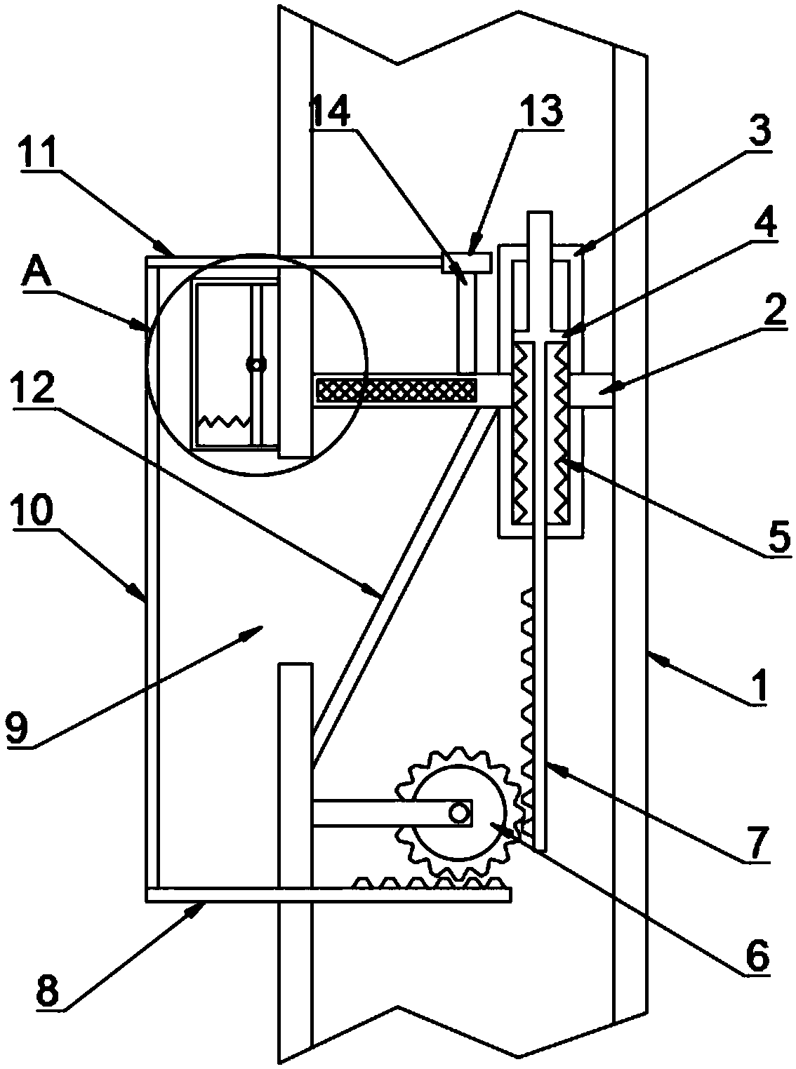
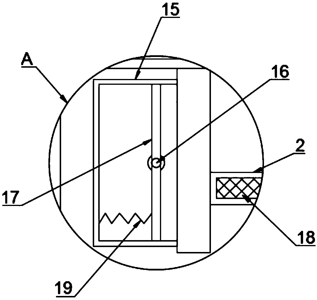
[0024] refer to Figure 1-2 , an anti-clogging sewer pipe, comprising a pipe 1, an installation plate 2 is fixed on the inner wall of the pipe 1, a first installation port and a second installation port are opened on the installation plate 2, a fixed pipe 3 is installed in the first installation port, the second A filter screen 18 is installed in the installation port, and a slide bar 7 slides in the fixed tube 3, and the outer wall of one end of the slide bar 7 located in the fixed tube 3 is provided with a flange 4, which is fixed between the flange 4 and the inner bottom wall of the fixed tube 3 A return spring 5 is connected, and the return spring 5 is set to ensure that the slide bar 7 can return to its original position under the reverse elastic force of the return spring 5 after it moves down. Extending to the outside of the fixed pipe 3, a mounting plate is fixed on the inner wall of the pipe 1, a gear 6 is installed on the end of the mounting plate away from the inner...

Embodiment 2

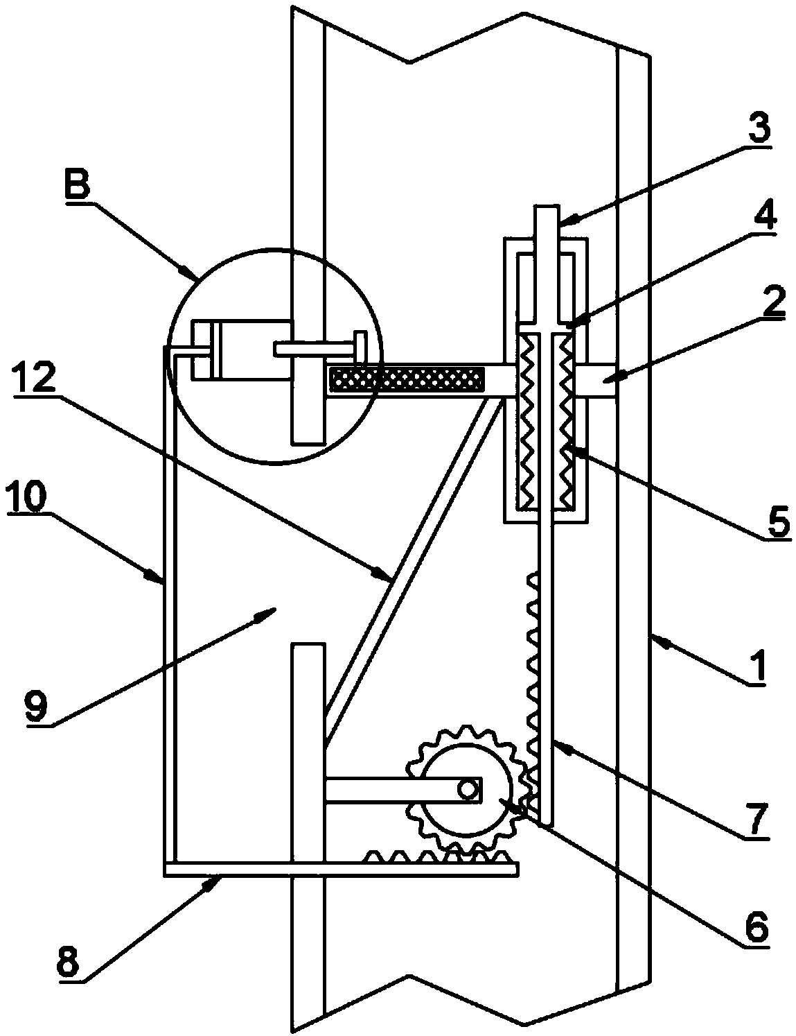
[0029] refer to Figure 3-4 , the difference from Embodiment 1 is that the cleaning mechanism includes a first moving rod 8 inserted in parallel on the outer wall of the pipeline 1, the first moving rod 8 is located on one side of the gear 6 and is arranged perpendicular to the sliding rod 7, the second A side wall of a moving bar 8 near the gear 6 is provided with a second sawtooth meshed with the gear 6, the outer wall of the pipeline 1 is fixed with an air bag 20, and the air bag 20 is slidably connected with a push plate 21, and the push plate 21 is connected to the first The moving rods 8 are connected by connecting rods 10. An air outlet pipe 22 is inserted in the airbag 20. The end of the air outlet pipe 22 away from the airbag 20 runs through the outer wall of the pipeline 1 and extends to the side of the filter screen 18 away from the gear 6. When the filter screen 18 When it is blocked, the water in the pipe 1 accumulates, the water pressure increases, and the slidin...


PUM


Abstract

The invention discloses an anti-blocking sewer pipeline which comprises a pipeline. A mounting disc is fixed to the inner wall of the pipeline, a first mounting opening and a second mounting opening are formed in the mounting disc, a fixing pipe is mounted in the first mounting opening, a filter screen is mounted in the second mounting opening, a slide bar is slidably arranged in the fixing pipe,a flange is arranged on the outer wall of the end, which is positioned in the fixing pipe, of the slide bar, a return spring is arranged between the flange and the inner bottom wall of the fixing pipein a fixedly connected manner, the lower end of the slide bar extends out of the fixing pipe, and a mounting plate is fixed onto the inner wall of the pipeline. The anti-blocking sewer pipeline has the advantages that water pressures can be increased after the inside of the pipeline is blocked, the slide bar can be squeezed to downwardly move, a first movable rod and a second movable rod furthercan be driven to move, blocking materials on the filter screen further can be scraped by a scraping plate and can be pushed into a collecting groove to be collected, accordingly, the smoothness of thefilter screen and the pipeline can be recovered, the anti-blocking sewer pipeline is convenient to clean, and normal family life can be guaranteed.

Description

technical field [0001] The invention relates to the technical field of sewer pipes, in particular to an anti-blocking sewer pipe. Background technique [0002] The sewer is a kind of urban public facility, which refers to the pipes for removing sewage and rainwater from buildings; it also refers to the underground channels for discharging sewage and rainwater in cities, factories or villages. [0003] Generally, the sewer pipes of sinks and vegetable sinks, etc., some of these pipes are accidentally dropped into foreign objects during installation or blocked by installation errors, and some of the pipes will be scaled during use, making the inner diameter of the pipes thinner and affecting normal operation. If the sewer is blocked, it will easily affect the normal progress of family life, and it is generally not easy to clean up. [0004] For this reason, we have proposed an anti-clogging sewer pipe to solve the above problems. Contents of the invention [0005] The purp...

Claims


Application Information

Patent Timeline
IPC IPC(8): E03C1/302
CPCE03C1/302
Inventor 胡健
Owner 管敏富
Why Eureka
Try Eureka