
Method for installing spatial-bending-joint discontinuous tubular truss

An installation method and continuous tube technology, applied to truss structures, truss beams, joists, etc., can solve the problems of low installation precision, high construction cost, and low efficiency, and achieve the effect of improving installation efficiency and ensuring construction quality

Inactive Publication Date: 2019-01-04
FANGCHENGGANG ZHONGYI HEAVY IND
View PDF5 Cites 1 Cited by
  • Summary
  • Abstract
  • Description
  • Claims
  • Application Information

AI Technical Summary

Problems solved by technology

[0002] At present, in the installation process of pipe trusses in large venues such as stadiums, railway stations, and terminal buildings, the traditional method often adopts the method of hoisting parts or small unit components. The defects of the traditional method are low installation precision, low efficiency, and high-altitude operations. The quantity is large, the operating personnel are dangerous, and the construction cost is high

Method used


Image

  • Method for installing spatial-bending-joint discontinuous tubular truss
  • Method for installing spatial-bending-joint discontinuous tubular truss

Examples


Embodiment Construction

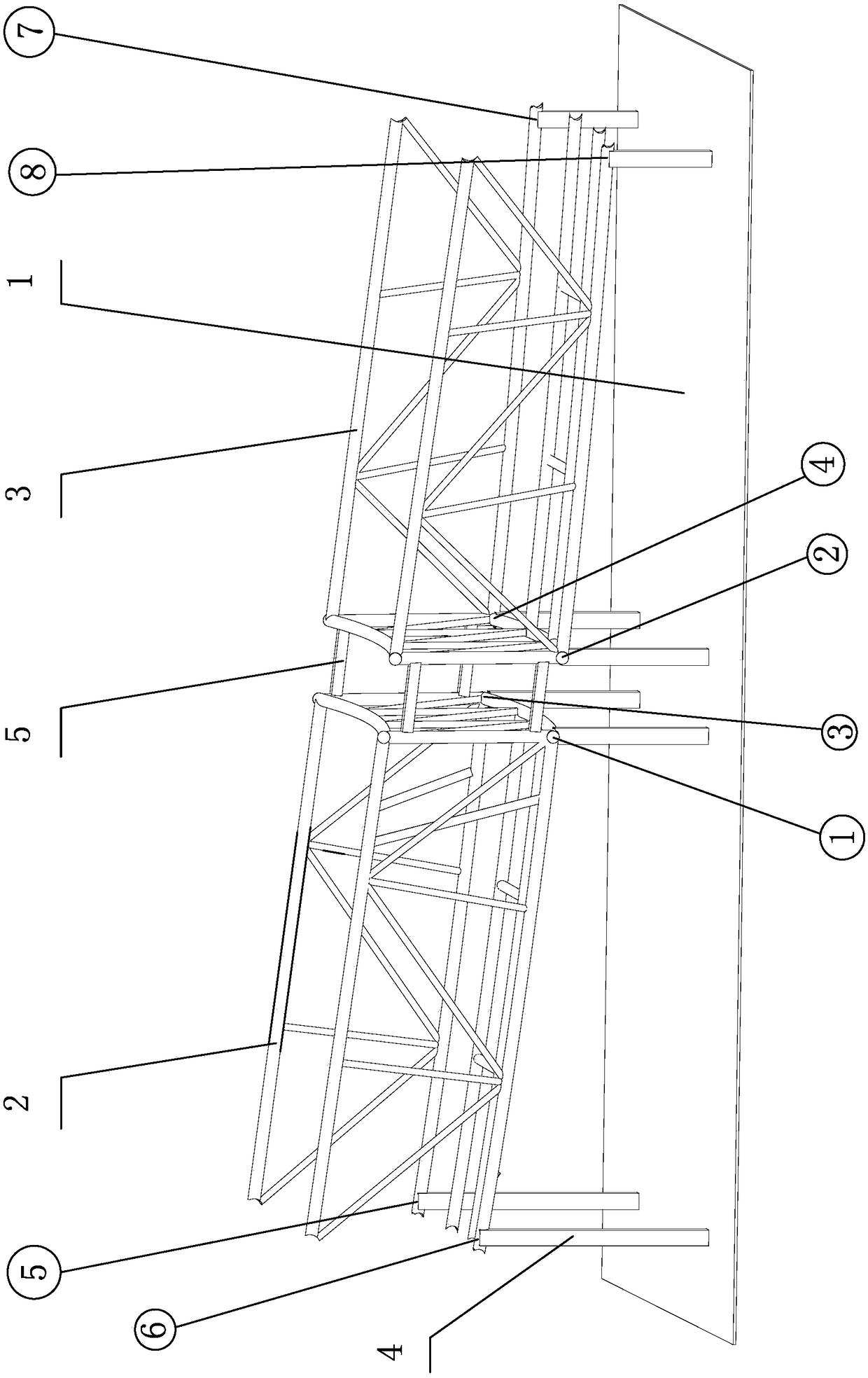
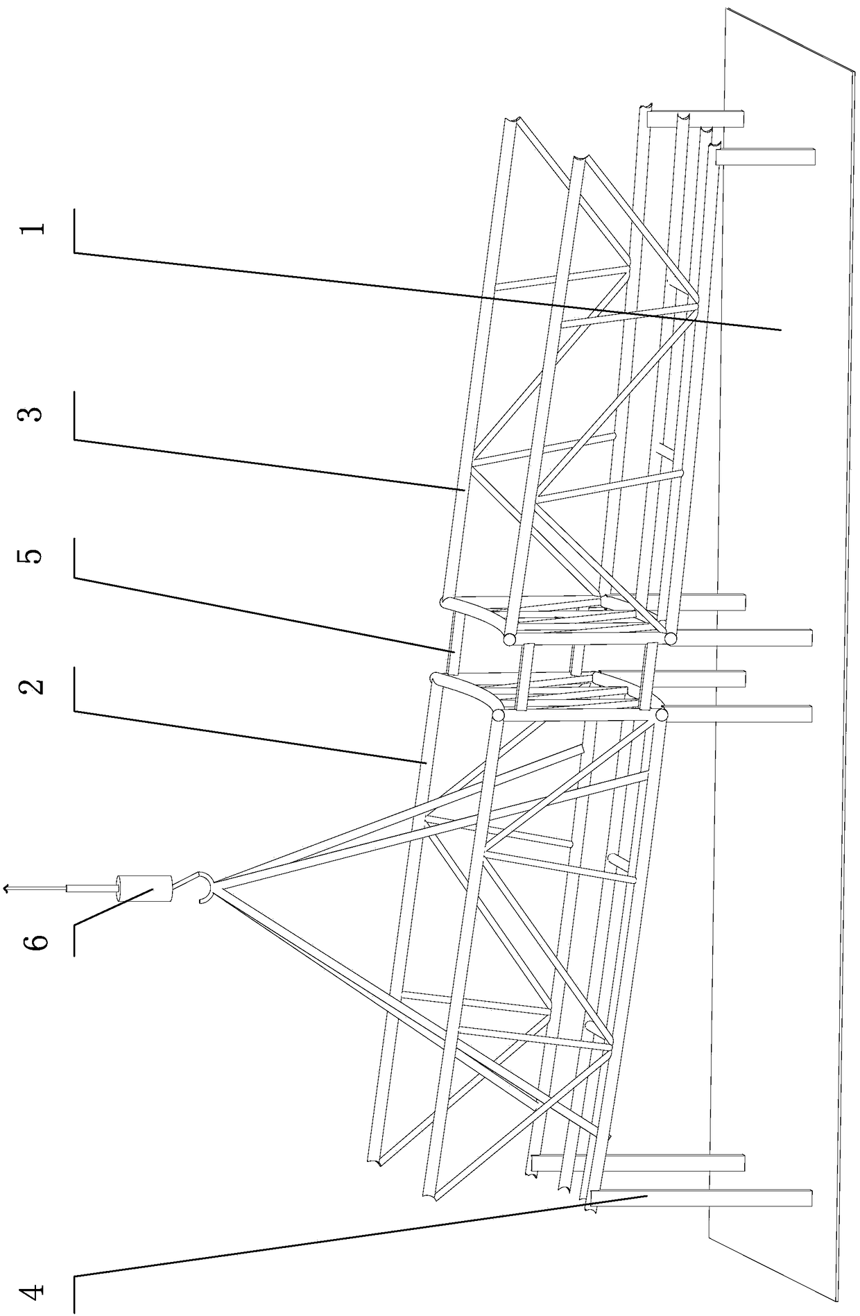
[0019] The technical solution of the present invention will be further described below in conjunction with the embodiment shown in the accompanying drawings (the front and rear pipe trusses 2, 3 are two discontinuous pipe trusses).

[0020] The installation method of the space bend discontinuous pipe truss of the present invention, its operating steps are:

[0021] 1. Level the site of the construction site, lay steel plates with a thickness of more than 10mm to build the assembly platform 1, adjust the uneven parts, and check the levelness of the assembly platform 1 with a level, so that the unevenness of the assembly platform 1 is ≦ 2mm.

[0022] 2. Calculate the spatial coordinate values ​​of 8 nodes ①, ②, ③, ④, ⑤, ⑥, ⑦, ⑧ on the front pipe truss 2 and the rear pipe truss 3, among which: nodes ①, ②, ③, ④ are the front , the relative left and right endpoints of the bottom of the rear pipe truss 2 and 3, the nodes ⑤ and ⑥ are the left and right breakpoints at the bottom of th...


PUM


Abstract

The invention discloses a method for installing a spatial-bending-joint discontinuous tubular truss. The method comprises: step one, steel plates are laid at a construction site and an assembling platform is built; step two, spatial coordinate values of nodes 1,2,3,4,5,6,7, and 8 of a front pipe truss and a rear pipe truss are calculated and the nodes 1,2, and 3 among the opposite nodes of the front pipe truss and the rear pipe truss form a reference surface; step three, altitude differences of the nodes 4, 5, 6, 7, and 8 relative to the reference surface and horizontal relative coordinates ofthe nodes are calculated based on the reference surface, and relative heights of all support columns in a front bed jig and a rear bed jig on the assembling platform are determined according to the relative coordinates of all nodes and the reference surface; step four, front and rear pipe truss assembling, welding and correction are carried out on support columns of the front bed jig and the rearbed jig respectively; and the front pipe truss and the rear pipe truss are fixedly connected by profile steel members; step five, overall hoisting, installation preparation, and welding are carried out on the front pipe truss and the rear pipe truss; and step six, the profile steel members are removed. Therefore, the construction quality and construction safety are ensured; the construction schedule and installation precision are improved; and the construction cost is lowered.

Description

technical field [0001] The invention relates to building construction installation technology, in particular to a space bending discontinuous pipe truss installation method. Background technique [0002] At present, in the installation process of pipe trusses in large venues such as stadiums, railway stations, and terminal buildings, the traditional method often adopts the method of hoisting parts or small unit components. The defects of the traditional method are low installation precision, low efficiency, and high-altitude operations. The quantity is large, the operating personnel are dangerous, and the construction cost is high. Contents of the invention [0003] Aiming at the deficiencies of the existing technology, the technical problem to be solved by the present invention is to propose a space bending discontinuous pipe truss installation method that improves construction efficiency, installation accuracy and quality of the pipe truss, reduces construction cost, and...

Claims


Application Information

Patent Timeline
Patent Type & Authority Applications(China)
IPC IPC(8): E04G21/14E04C3/02
CPCE04C3/02E04G21/14
Inventor 赵保华王连想闫毫辉张锐
Owner FANGCHENGGANG ZHONGYI HEAVY IND
Learn More